
Manipulator

A technology of manipulators and base plates, applied in the field of manipulators, can solve the problems that ordinary manipulators are not flexible enough

Inactive Publication Date: 2019-05-07
钟光远
View PDF0 Cites 0 Cited by
  • Summary
  • Abstract
  • Description
  • Claims
  • Application Information

AI Technical Summary

Problems solved by technology

[0005] The primary purpose of the present invention is to solve the shortcoming that common manipulators are not flexible enough

Method used


Image

  • Manipulator

Examples


Embodiment Construction

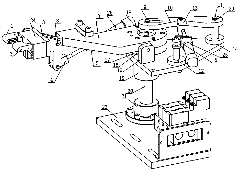
[0011] Referring to the accompanying drawings, the manipulator of the present application includes a base plate 22, a flange plate 21 is provided on the base plate 22, a column 20 is provided on the flange plate 21, an adjusting sleeve 19 is provided on the column 20, and the adjusting sleeve 19 is threadedly connected with the column 20, The adjusting sleeve 19 is provided with a fixed plate 14, the connecting rod 10 is arranged on the fixed plate 1 through the pin one 11 and the jumper 29, the cylinder one 25 is connected with the pin two 12 arranged on the fixed plate through the cylinder hinge one 5, and the cylinder A 25 cylinder head-13 connects the connecting rod 10; the fixed plate 14 is also provided with a spacer 17, and the base 16 is arranged on the spacer 17, and the base 16 is provided with a swing arm 7, and the swing arm 7 can surround the axis of rotation 18 rotates, and the swing arm 7 is also provided with a protruding shaft 9 to cooperate with the correspond...


PUM


Abstract

The invention discloses a manipulator. The manipulator comprises a base plate; a flange plate is arranged on the base plate, and is provided with a stand column; an adjusting sleeve is arranged on thestand column, and is in threaded connection with the stand column; a fixed plate is arranged on the adjusting sleeve; a connecting rod is arranged on the fixed plate through a first pin shaft and a clamping spring; a first cylinder is connected with a second pin shaft arranged on the fixed plate through a first cylinder hinge; a first cylinder head of the first cylinder is connected with the connecting rod; a spacing ring is arranged on the fixed plate; a base is arranged on the spacing ring, and is provided with a rotating arm; the rotating arm can be rotated around a rotating shaft; and therotating arm is provided with a convex tension shaft matched with a corresponding groove in the connecting rod. The front part of the rotating arm is connected with a connecting device through a first rotating shaft; a connecting block is arranged at one end of the connecting device, and is provided with a pneumatic finger; a left clamping block and a right clamping block are arranged on the pneumatic finger; and the pneumatic finger can drive the left clamping block and the right clamping block to clamp or release workpieces. The rotating arm is fixedly connected with a cylinder; and the cylinder is connected with the other end of the connecting device through a second rotating shaft.

Description

technical field [0001] This application relates to a manipulator. Background technique [0002] Conventional manipulators usually can only rotate around one axis, and the degree of freedom is not enough, so it is necessary to improve it. Contents of the invention [0003] The present invention provides a manipulator to overcome at least one defect described in the above prior art. [0004] The present invention aims to solve the above-mentioned technical problems at least to a certain extent. [0005] The primary purpose of the present invention is to solve the shortcoming that common manipulators are not flexible enough. [0006] In order to solve the problems of the technologies described above, the technical solution of the present invention is as follows: [0007] The manipulator of the present application includes a bottom plate, a flange plate is arranged on the bottom plate, a column is arranged on the flange plate, an adjusting sleeve is arranged on the column...

Claims


Application Information

Patent Timeline
Patent Type & Authority Applications(China)
IPC IPC(8): B25J15/08B25J9/00
Inventor 钟光远
Owner 钟光远
Learn More