
Tunneling roadway rapid supporting equipment and working method thereof

A roadway and fast technology, applied in mining equipment, earthwork drilling, mine roof support, etc., to reduce labor intensity, increase stability, and reduce damage

Inactive Publication Date: 2022-03-25
LIAONING TECHNICAL UNIVERSITY
View PDF0 Cites 0 Cited by
  • Summary
  • Abstract
  • Description
  • Claims
  • Application Information

AI Technical Summary

Problems solved by technology

[0004] The purpose of the present invention is to provide a rapid support equipment for tunneling roadway and its working method to solve the related problems raised in the above-mentioned background technology, and at the same time, it can improve the efficiency of anchoring work on the tunneling face, reduce the labor intensity of workers and improve the efficiency of workers. Safety at work

Method used


Image

  • Tunneling roadway rapid supporting equipment and working method thereof
  • Tunneling roadway rapid supporting equipment and working method thereof
  • Tunneling roadway rapid supporting equipment and working method thereof

Examples


Embodiment 1

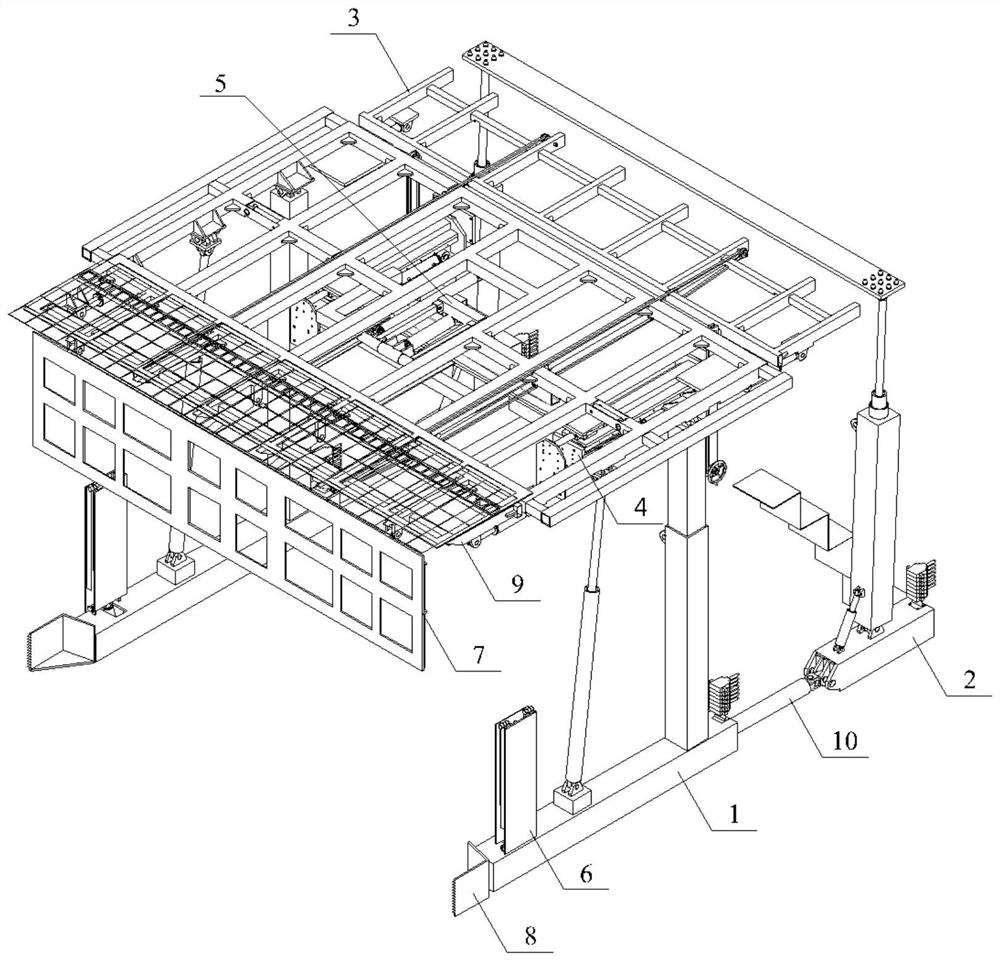
[0065] see Figure 1-7 , the present invention provides a technical solution: a rapid support equipment for tunneling roadway, including:

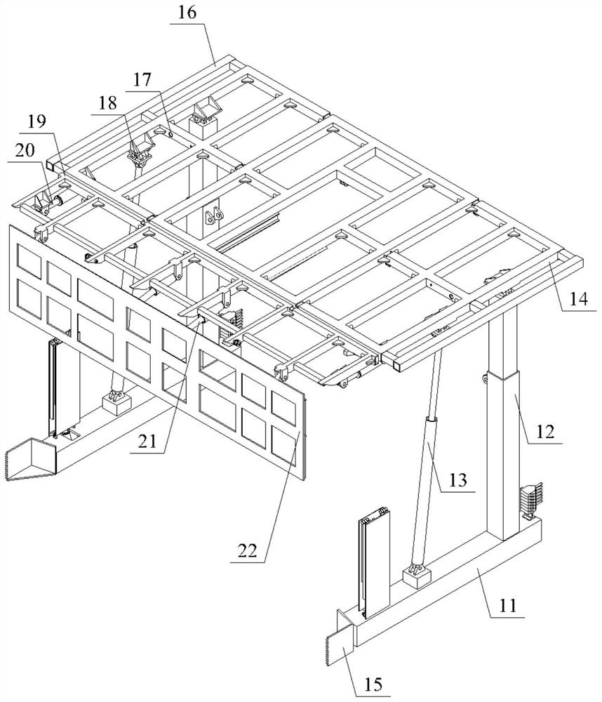
[0066] The first support frame unit 1 includes: a first support frame base 11, a first support frame guide support 12 and a first support frame top beam 14, one end of the first support frame guide support 12 and the first support frame base 11 is fixedly connected, and the other end is hinged to the top beam 14 of the first support frame;

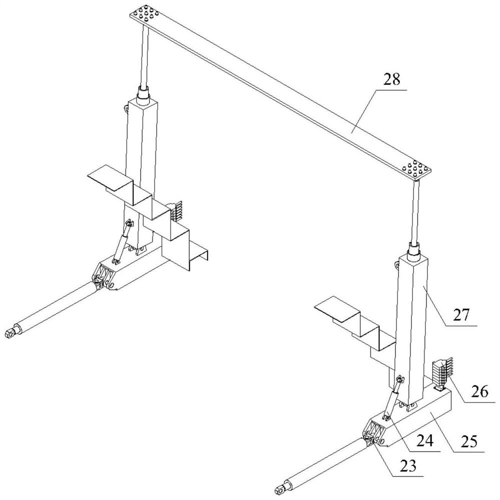
[0067] The second support frame unit 2 is connected to the first support frame base 11 through a connection mechanism, and the first support frame unit 1 and the second support frame unit 2 can slide relatively. In this implementation, the connection mechanism adopts Bottom push-pull oil cylinder 10, in other embodiments, also can adopt other devices as required;

[0068] The operating mechanism 26 and the power mechanism are used to control the operation of the rapid support equipment for the excava...

Embodiment 2

[0080] A rapid support device for tunneling in this embodiment is further improved on the basis of Embodiment 1. The multi-degree-of-freedom drilling rig moving mechanism 5 includes:

[0081] The horizontal chute 38 is arranged along the axial direction of the roadway, and is fixed below the top beam 14 of the first support frame;

[0082] A horizontal slider 40 is arranged in the horizontal chute 38 and is slidably connected with the horizontal chute 38;

[0083] The beam 42 is arranged below the horizontal chute 38 and connected with the horizontal slider 40 through the connecting frame 41;

[0084] The transverse chute 39 is opened on the beam 42, and the rock bolt unit 4 is slidably connected in the transverse chute 39, so that the rock bolt unit 4 has a transverse degree of freedom.

Embodiment 3

[0086] The rapid support equipment for tunneling roadway in this embodiment is further improved on the basis of Embodiment 1, and the first support frame unit 1 also includes:

[0087] The first support frame is inclined to support 13, one end is hinged to the first support frame base 11, and the other end is hinged to the first support frame top beam 14. In this implementation, the first support frame is inclined to support 13 through the first support frame The crosshead 18 is hinged on the top beam 14 of the first support frame, and in other embodiments, other structures can also be adopted as required;

[0088] The anchoring operation platform 6 is arranged on the base 11 of the first support frame.


PUM


Abstract

The invention discloses rapid supporting equipment for tunneling roadways and a working method thereof, and the equipment comprises a first supporting frame unit, a second supporting frame unit, an anchor rod drilling unit arranged below the first supporting frame unit, and an auxiliary material conveying mechanism arranged above the first supporting frame unit, the control mechanism and the power mechanism are used for controlling the operation of the rapid supporting equipment for tunneling roadways. The forepoling function is enriched, a power system is distributed, the forepoling device can be matched with a heading machine for use, further transformation is not needed, and the forepoling device has the advantages of being easy to operate, low in price, high in adaptability and the like.

Description

technical field [0001] The invention relates to the technical field of coal mine machinery design, in particular to a rapid support device for tunneling roadway and a use method thereof. Background technique [0002] With the development of science and technology, intelligent coal mines have gradually become the mainstream. Advanced support equipment is an important part of intelligent coal mines. However, the price of advanced support equipment is relatively expensive. Although the hydraulic support is very powerful, its high cost The price and high after-sales costs are also unaffordable for some small and medium-sized coal mines, so some small and medium-sized coal mines are still using old or non-compliant hydraulic supports, which has great potential safety hazards, and even Coal Mine Safety Accident. [0003] Part of the existing advance support adopts the form of front support and rear anchorage. Due to the length of the fuselage is too long and the structure is too ...

Claims


Application Information

Patent Timeline
Patent Type & Authority Applications(China)
IPC IPC(8): E21D23/04E21D23/08E21D20/00E21F13/00
CPCE21D23/04E21D23/0472E21D23/08E21D20/003E21F13/006
Inventor 谢苗李佩达卢进南刘治翔毛君高建王贺董钰峰李玉岐
Owner LIAONING TECHNICAL UNIVERSITY
Learn More