
Gravitational wave detecting device

A detection device and gravitational wave technology, applied in the field of optical measurement, can solve problems such as the limitation of the length of the resonator rod, the high power requirement of the laser light source, and the impact on the stability of the system

Active Publication Date: 2005-12-28
HUAZHONG UNIV OF SCI & TECH
View PDF0 Cites 0 Cited by
  • Summary
  • Abstract
  • Description
  • Claims
  • Application Information

AI Technical Summary

Problems solved by technology

The disadvantage is: due to the resonance effect, it only has the best detection sensitivity for the resonance frequency. At the same time, the resonance effect makes the length of the resonant rod limited, and the length of the resonant rod can only be half of the wavelength of the sound wave.
The disadvantage is that it has no resonant mass as a carrier, so it does not use the resonance effect to amplify the gravitational wave signal. In addition, the back and forth folding of the optical path requires a high power of the laser light source, and the large size of the whole device also affects the stability of the system.

Method used


Image

  • Gravitational wave detecting device
  • Gravitational wave detecting device

Examples


Embodiment Construction

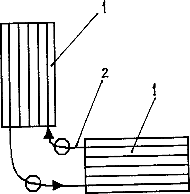
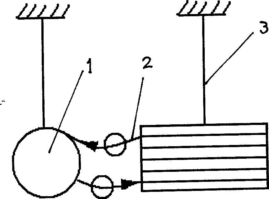
[0016] figure 1 and figure 2 In the figure, there is an optical fiber 2 on the resonant rod 1, which is suspended by the string wire 3. The circles in the figure represent various optical devices, including amplifiers, interferometers, optical pulse injection, and timing detection of optical pulses. Arrows indicate optical pulse signals.

[0017] Take typical parameter values ​​as an example: take two quartz cylinders made of the same material as the optical fiber 2 as the resonant rod 1 . The length of the cylinder is L=2 meters, the diameter D=0.5 meters, and another optical fiber with a length of S=200 kilometers and a diameter of d=8 microns is taken. Divide the optical fiber into two sections; each section is folded into N=50,000 small sections, and placed inside the resonant rod along the axis of the resonant rod, or attached to the surface of the resonant rod. The ends of the optical fibers are connected by optical devices, and the entire optical fiber with a length...


PUM


Abstract

The gravitational wave detection device belongs to the field of optical measurement technology, which not only utilizes the resonance effect but also utilizes the extended optical path to amplify the gravitational wave signal, so as to improve the sensitivity of detecting gravitational wave. In the present invention, the two resonant rods are independently hung horizontally through the center by strings, and their central axes are perpendicular to each other; corresponding to the two resonant rods, the optical fiber is divided into two sections, and each section is folded into N subsections, 1,000≤N ≤1,000,000, and wound along the axis of the resonant rod and fixed on the resonant rod, or placed in the resonant rod along the axis of the resonant rod, the ends of the optical fibers on the two resonant rods are connected by optical devices, and the entire optical fiber forms a closed loop. The resonant rod and the optical fiber on it act as a resonant mass, and use the resonance effect to amplify the gravitational wave signal by Q times; at the same time, the optical fiber folding is used to greatly increase the optical path of the optical signal, and the response of the resonant rod to the gravitational wave is accumulated to enhance the detection of gravitational waves. ability to further amplify the gravitational wave signal and greatly improve the detection sensitivity.

Description

technical field [0001] The invention belongs to the technical field of light measurement. Background technique [0002] Gravitational waves are a phenomenon predicted by the general theory of relativity to propagate fluctuations in the curvature of space-time. Since the source of gravitational waves is very far away from the solar system, the gravitational waves projected to the earth are generally extremely weak. The direct detection of gravitational waves is very difficult experimentally: the weak object to be measured places high requirements on the sensitivity of the detection instrument. So far there is no direct evidence of gravitational waves being observed. Two types of detectors have been built to detect gravitational waves, resonant mass detectors and laser interferometer detectors. [0003] Resonant mass detectors use the resonance between resonant mass and gravitational waves to detect gravitational waves, literature M.Bassan Resonant gravitational wave detect...

Claims


Application Information

Patent Timeline
Patent Type & Authority Patents(China)
IPC IPC(8): G01V7/00
Inventor 罗俊刘中柱
Owner HUAZHONG UNIV OF SCI & TECH
Learn More