
ECG tester

A detection device and electrocardiogram technology, applied in diagnostic recording/measurement, medical science, sensors, etc., can solve problems such as difficulty in distinguishing P waves, distance from the grounding point, and difficulty in coordinating electrical activities, so as to overcome the right ventricular blind zone, The effect of high performance of the core wire and the improvement of the correct diagnosis rate

Inactive Publication Date: 2005-11-02
SOUTHERN MEDICAL UNIVERSITY
View PDF0 Cites 0 Cited by
  • Summary
  • Abstract
  • Description
  • Claims
  • Application Information

AI Technical Summary

Problems solved by technology

[0015] Furthermore, each reference point is far away from the ground point, and the electrical activities between the two are difficult to coordinate, which is also not conducive to the correct expression of the positive input signal.
[0016] It is precisely because of the above-mentioned disadvantages that the conventional lead system has always existed. Therefore, although clinical electrocardiography has been studied by several generations for a hundred years, it is still at the level of an empirical discipline today, and it still cannot solve the following defects caused by the above-mentioned disadvantages , that is, right ventricular blind zone, indistinguishable P wave, pseudo-change, inaccurate positioning and floating standard
Because of this, the correct diagnosis rate of electrocardiogram recorded by all clinical electrocardiographs at home and abroad is only 60-70% for myocardial infarction, and the coincidence rate for the diagnosis of right ventricular hypertrophy is only about 30%.

Method used


Image

  • ECG tester
  • ECG tester
  • ECG tester

Examples


Embodiment Construction

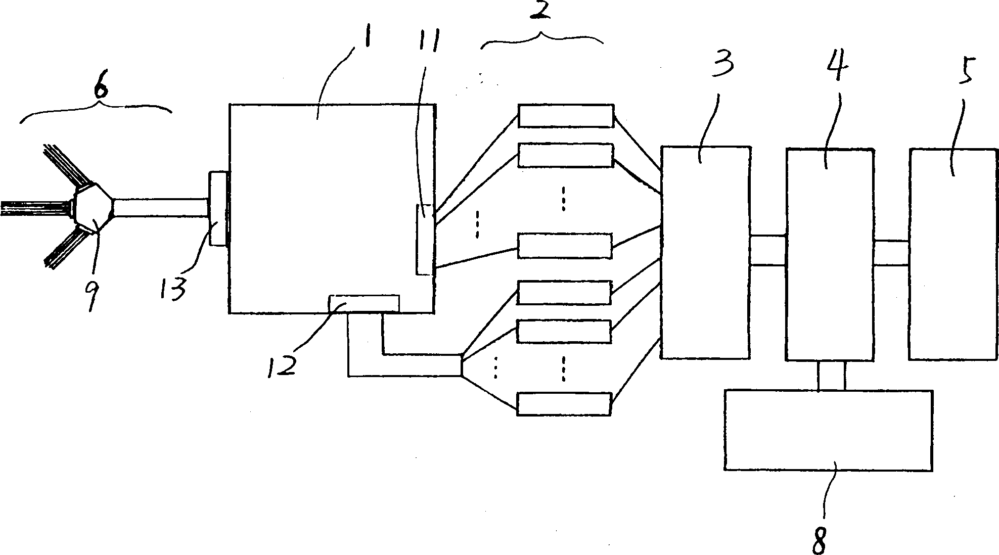
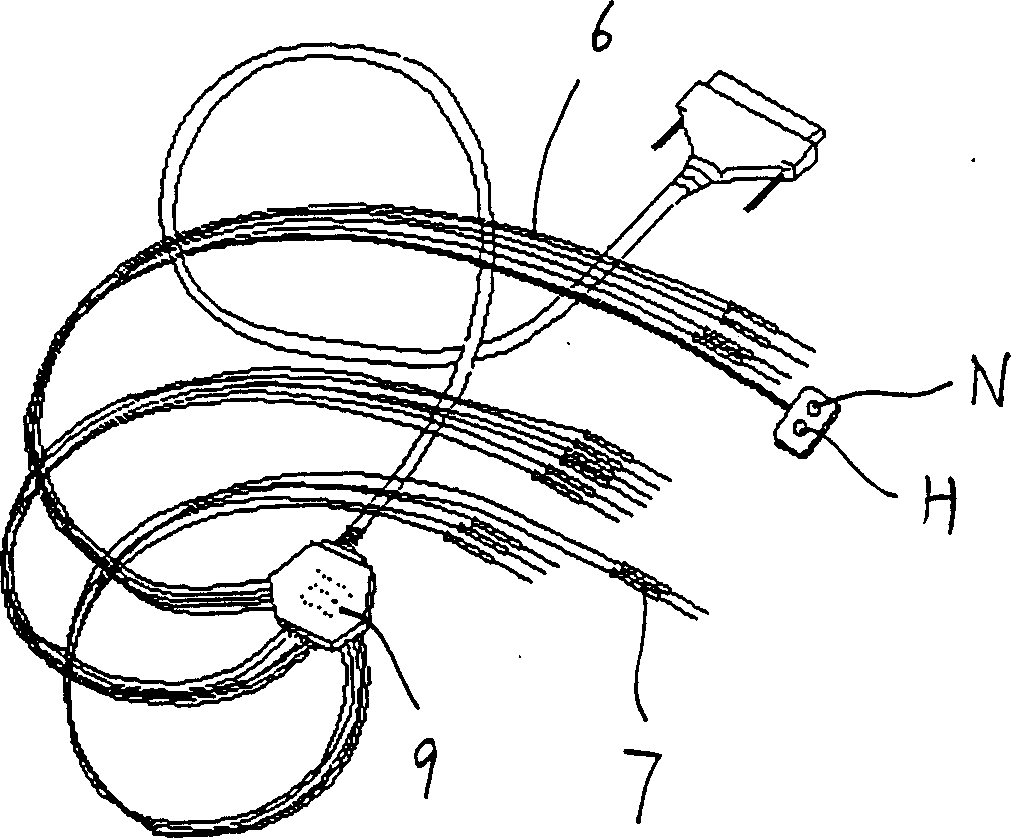
[0025] See figure 1 , The electrocardiogram detection device of the present invention includes at least a network board 1, an amplifier 2, an analog-to-digital conversion device 3, a computer host 4, a display 5, a lead cable 6 and electrodes 7 (see image 3 ), and other auxiliary equipment 8 (such as printers, etc.).

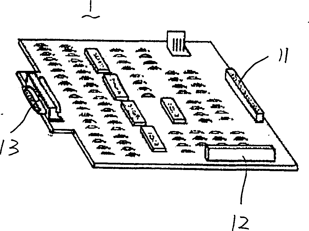
[0026] See also figure 1 with figure 2 , The network board 1 is equipped with an analog signal transmission circuit and a branching circuit (not shown), and a number of connection ports 11, 12, 13 for electrically connecting the lead cable 6, the amplifier 2 and the network board 1. Among them, The connection port 11 is used for the 12-channel conventional lead ECG signal output of the conventional lead, the connection port 12 is used for the 12-channel head chest lead ECG signal output of the head-chest lead, and the connection port 13 is used for the lead cable 6 transmission. For signal input. The amplifier 2 is divided into two groups: a conventional lead amp...


PUM


Abstract

An electrocardiography is composed of a network board with relative circuit, amplifiers, A / D converter, computer, display, leading cable and electrodes. Said leading cable contains the conductors for transferring conventional cardioelectric signals and the conductors for transferring the cardioelectric signals of head and chest. Said electrodes are respectively used for the signals of limbs, chest, back, waist, abdomen, head and grounding. Said network board has conventional 12 terminals and additional 12 terminals for head and chest signals, which are respectively connected to relative conductors in cable and amplifiers. Its advantages is higher correctness.

Description

【Field of Invention】 [0001] The invention relates to an electronic medical detection device, in particular to an electrocardiogram detection device. [Background of the invention] [0002] The existing electrocardiogram detection devices are designed in accordance with the conventional 12-lead electrocardiogram detection method that has been standardized for a hundred years. There are analog electrocardiographs, which are composed of an electrocardiogram amplifier, a pen recorder, a lead cable and their corresponding ground electrodes ( Such as the 6511 electrocardiograph); there is a digital electrocardiograph, which is composed of an ECG amplifier, a sampling board, a microcomputer, a thermal array recorder, a lead cable and its corresponding connecting electrode and a ground electrode. The latter is divided into two categories: portable electrocardiographs intelligently controlled by a single-chip computer and desktop electrocardiographs intelligently controlled by a PC, often ...

Claims


Application Information

Patent Timeline
Patent Type & Authority Patents(China)
IPC IPC(8): A61B5/0402
Inventor 尹炳生李本富喻德旷农德斌
Owner SOUTHERN MEDICAL UNIVERSITY
Learn More