
Printer

A technology of printers and ports, applied in the field of printers, can solve the problems of inability to modify and upgrade printer controllers, and high cost, and achieve the effects of convenient upgrades, cost savings, and configuration chips

Inactive Publication Date: 2005-09-14
宏电脑上海
View PDF0 Cites 2 Cited by
  • Summary
  • Abstract
  • Description
  • Claims
  • Application Information

AI Technical Summary

Problems solved by technology

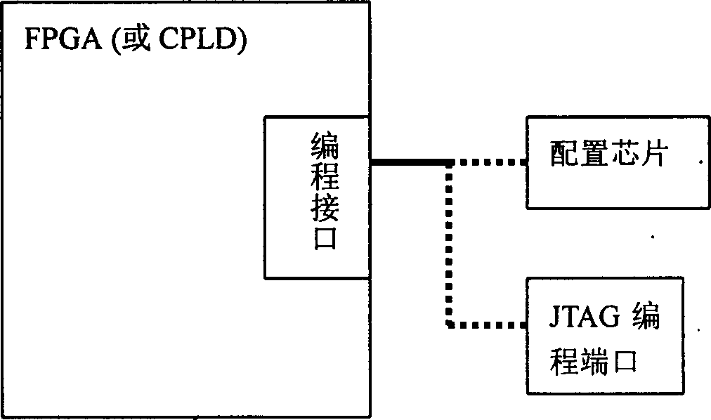
Therefore, when this kind of printer corrects or upgrades the controller hardware logic, not only the cost is high, but also the user cannot correct and upgrade the printer controller by himself, and professional maintenance personnel are needed to complete the reprogramming work

Method used


Image

  • Printer
  • Printer
  • Printer

Examples


Embodiment Construction

[0028] This section gives a specific example of the present invention.

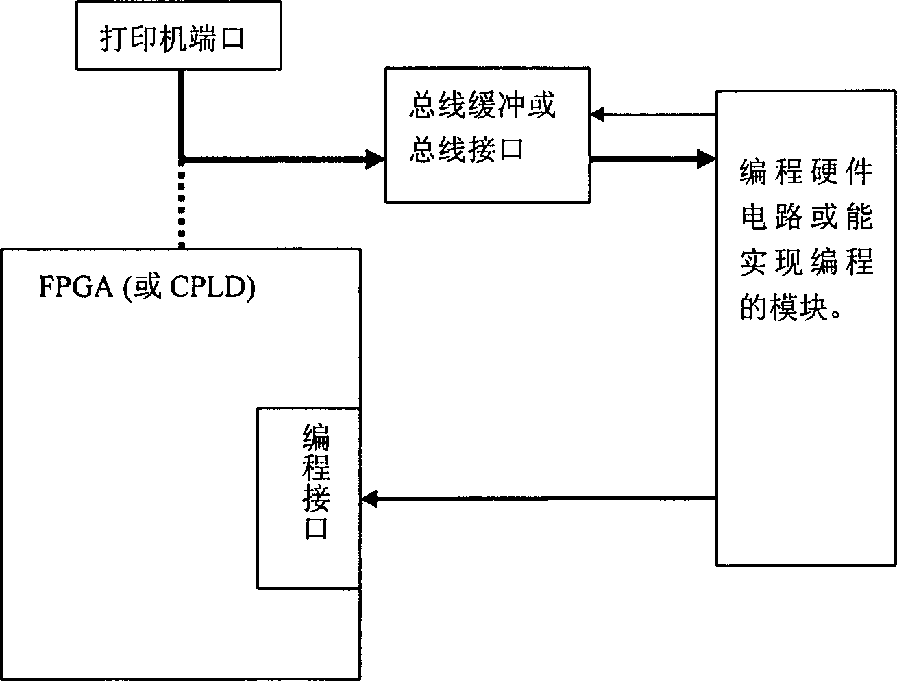
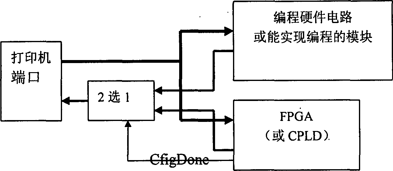
[0029] Printers, including printer controllers that use programmable devices FPGA or CPLD for hardware logic configuration, such as figure 2 As shown, the programmable device FPGA or CPLD communicates with the printer port protocol, and the configuration file is written through the printer port. The printer controller has a built-in programming hardware circuit or a module that can realize programming. This module communicates with the printer port through the bus buffer and bus interface, and is used to write the configuration file data written by the printer port according to the programmable device FPGA or CPLD. The programming interface timing is written into the programmable device FPGA or CPLD.

[0030] The printer port used in the example may be an IEEE1284 port, a USB port or a Standard TCP / IP port.

[0031]For IEEE1284 ports and Standard TCP / IP ports, the programming function ConfigFpga() or C...


PUM


Abstract

A printer has a printer controller using FPGA or CPLD for its hardware logic configuration. The said printer controller has a built-in programming hardware circuit or programming module communicated with printer port via bus buffer and bus interface and can write a configuration file from printer port to said FPGA or CPLD. If it is needed to update or upgrade current printer controller, user can only run the update program or upgrade program provided by printer factory.

Description

Technical field: [0001] The invention belongs to the technical field of printing equipment, and in particular relates to a printer controller including a programmable device FPGA (Programmable Gate Array, Field Programable Gate Array) or CPLD (a programmable logic device with parallel lines, Complex Programmable Logic Device) design printer. Background technique: [0002] With the significant increase in FPGA integration of programmable devices (a single chip can reach tens of millions of gates) and the sharp drop in price (less than 1$ per thousand LC), programmable devices are increasingly used in printer controllers , especially when the mass production of printer controllers cannot reach large quantities (such as less than 100K / year), it is more cost-effective to use programmable devices than to put into production ASIC chips; Carry out correction or upgrade without replacing the printer controller, reduce the risk of putting into production ASIC chips, and shorten the ...

Claims


Application Information

Patent Timeline
Patent Type & Authority Patents(China)
IPC IPC(8): G06F13/14
Inventor 徐忠良陈文先
Owner 宏电脑上海
Learn More