Plant waveguide and optical fibre low-loss connecting method

A technology of planar optical waveguide and connection method, which is applied in the coupling of optical waveguide, optical waveguide, etc., can solve the problems of increased coupling loss between waveguide and optical fiber, difference in cladding refractive index, etc., and achieves low polarization-dependent loss and good capacitance Poor characteristics, the effect of reducing coupling loss

Inactive Publication Date: 2005-07-27
ZHEJIANG UNIV
View PDF0 Cites 5 Cited by
  • Summary
  • Abstract
  • Description
  • Claims
  • Application Information

AI Technical Summary

Problems solved by technology

With the increasing complexity of optical integrated devices, due to the constraints of chip size and other factors, the difference between the refractive index of the core layer of the waveguide and the refractive index of the cladding layer is generally increased. In order to maintain the single-mode waveguide, it is necessary to reduce the cross-sectional size of the waveguide, which is Causes increased coupling loss of the waveguide and fiber butt joint

Method used


Image

  • Plant waveguide and optical fibre low-loss connecting method
  • Plant waveguide and optical fibre low-loss connecting method
  • Plant waveguide and optical fibre low-loss connecting method

Examples


Embodiment Construction

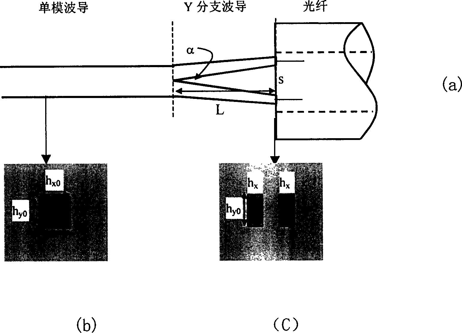
[0023] In the following, the buried waveguide is taken as an example to describe the implementation manner in detail. figure 1 In the specific connection method shown, at the end of the single-mode waveguide connected to the optical fiber, the single-mode waveguide is gradually separated into two waveguides with a certain distance and width to form a Y-shaped branch waveguide, and the branch of the waveguide is a sharp angle. alpha. Suppose the width and height of the original single-mode waveguide are h x0 and h yo , then the parameters of the branched waveguide are: branched waveguide length L, branched waveguide width h x and the distance s between the branch ends.

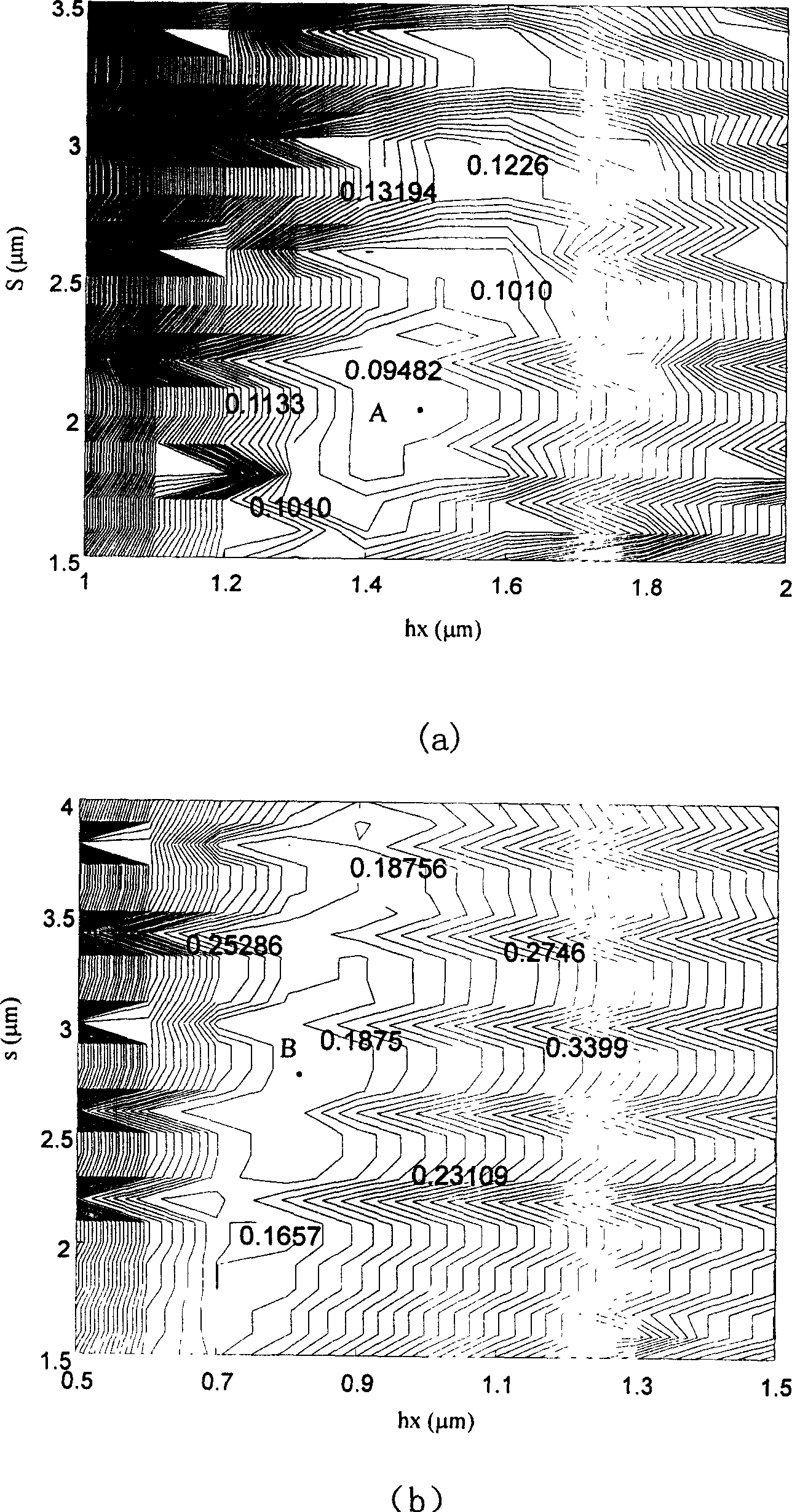
[0024] As for the length L of the branch waveguide, it is sufficient to ensure that the optical field changes slowly during the transmission process, generally in the range of 500 μm to 1000 μm. And the branch waveguide width h x The reasonable selection of the spacing s between the branch end and the bran...


PUM


Abstract

In the method the waveguide with bisect structure is connected to optical fibre at tail end of single-mode waveguide. The light mode spot is gradually changed to match with optical fibre intrinsic mode spot to decrease couple losses for butt-joint of optical waveguide with optical fibre when the light is transmitted from single-mode waveguide to branch waveguide and then transmitted along with the branch waveguide structure.

Description

technical field [0001] The invention relates to a method for connecting an optical waveguide and an optical fiber. Background technique [0002] Optical integrated devices have important applications in information processing such as optical communication. Among the many materials and waveguide structures that constitute optical integrated devices, optical waveguides represented by silica waveguide materials have a wide range of applications. In a device with a simple structure, the refractive index difference between the waveguide core layer and the cladding layer is very small, which belongs to the weak confinement waveguide, so the cross-sectional size of the waveguide is large, and the loss of the connection with the optical fiber is small. With the increasing complexity of optical integrated devices, due to the constraints of chip size and other factors, the difference between the refractive index of the core layer of the waveguide and the ref...

Claims


Application Information

Patent Timeline
Patent Type & Authority Patents(China)
IPC IPC(8): G02B6/14G02B6/26
Inventor 王谦何赛灵何建军
Owner ZHEJIANG UNIV
Why Eureka
Try Eureka