Blower and air conditioner with the same

An air conditioner and blower technology, applied in the fields of blowers and air conditioners, can solve the problems of reducing air supply efficiency, deteriorating aerodynamic characteristics of blades 23, increasing electric power consumption of motor 24, etc., so as to suppress the reduction of static pressure characteristics, Improved aerodynamics and reduced electric power consumption

Inactive Publication Date: 2005-05-11
DAIKIN IND LTD
View PDF0 Cites 0 Cited by
  • Summary
  • Abstract
  • Description
  • Claims
  • Application Information

AI Technical Summary

Problems solved by technology

[0005] However, when such a blade 23 is constituted by continuously changing its "camber" from the leading edge 23a to the trailing edge 23b, the following problem occurs: it is possible to increase the volume of the wake A0 discharged rearward from the trailing edge 23b of the blade 23. range, which deteriorates the aerodynamic characteristics of the blade 23 and reduces the air supply efficiency
[0006] In other words, since the convex surface is continuous on the negative pressure surface 23d side of the blade 23, as a result, the boundary layer on the negative pressure surface 23d gradually develops from the leading edge 23a to the trailing edge 23b. Next to the rear edge 23b, the airflow A flowing along the negative pressure surface 23d among the airflows flowing on the side of the negative pressure surface 23d 2 Separation occurs, and as a result, the wake A0 discharged from the rear side of the trailing edge 23b becomes unstable and becomes turbulent
On the other hand, on the side of the pressure surface 23c of the blade 23, since the angle difference between the airflow blowing direction of the trailing edge 23b (that is, the direction tangential to the curved surface near the trailing edge 23b) and the direction of rotation of the blade 23 becomes large, Airflow A flowing along the pressure surface 23c and discharged rearward from the rear edge 23b among the airflows passing through the side of the pressure surface 23c 1 , because after being discharged from the trailing edge 23b, it is subjected to the deflection effect along the direction of blade rotation, so its flow is unstable and prone to turbulent flow, which merges with the above-mentioned wake A0, which promotes the turbulence of wake A0, making The width of the airflow in the thickness direction of the blade, that is, the wake width S becomes larger
[0007] As a result, in the above-mentioned blades 23, the aerodynamic resistance thereof is increased, which not only reduces the air blowing efficiency of the blower as a whole, but also increases the electric power consumption of the motor 24 due to the reduced air blowing efficiency.
[0008] This increase in power consumption of the air blower is relatively easy to recognize when the air blower is used as a single unit. The electric power consumption of the air blower is very small compared with the electric power consumption of other components such as the compressor. Therefore, when studying the electric power consumption of the air conditioner as a whole from the perspective of energy saving, the compressor with the large electric power consumption is the most eye-catching, while the air blower’s Electrical power consumption hardly poses a problem

Method used


Image

  • Blower and air conditioner with the same
  • Blower and air conditioner with the same
  • Blower and air conditioner with the same

Examples


Embodiment Construction

[0038] Below, refer to Figure 1 ~ Figure 1 3 and Figure 14 ~ Figure 16 Explain the implementation form of the present invention, in Figure 1 ~ Figure 1 In 3, the same parts are marked with the same reference symbols.

[0039] The first implementation form

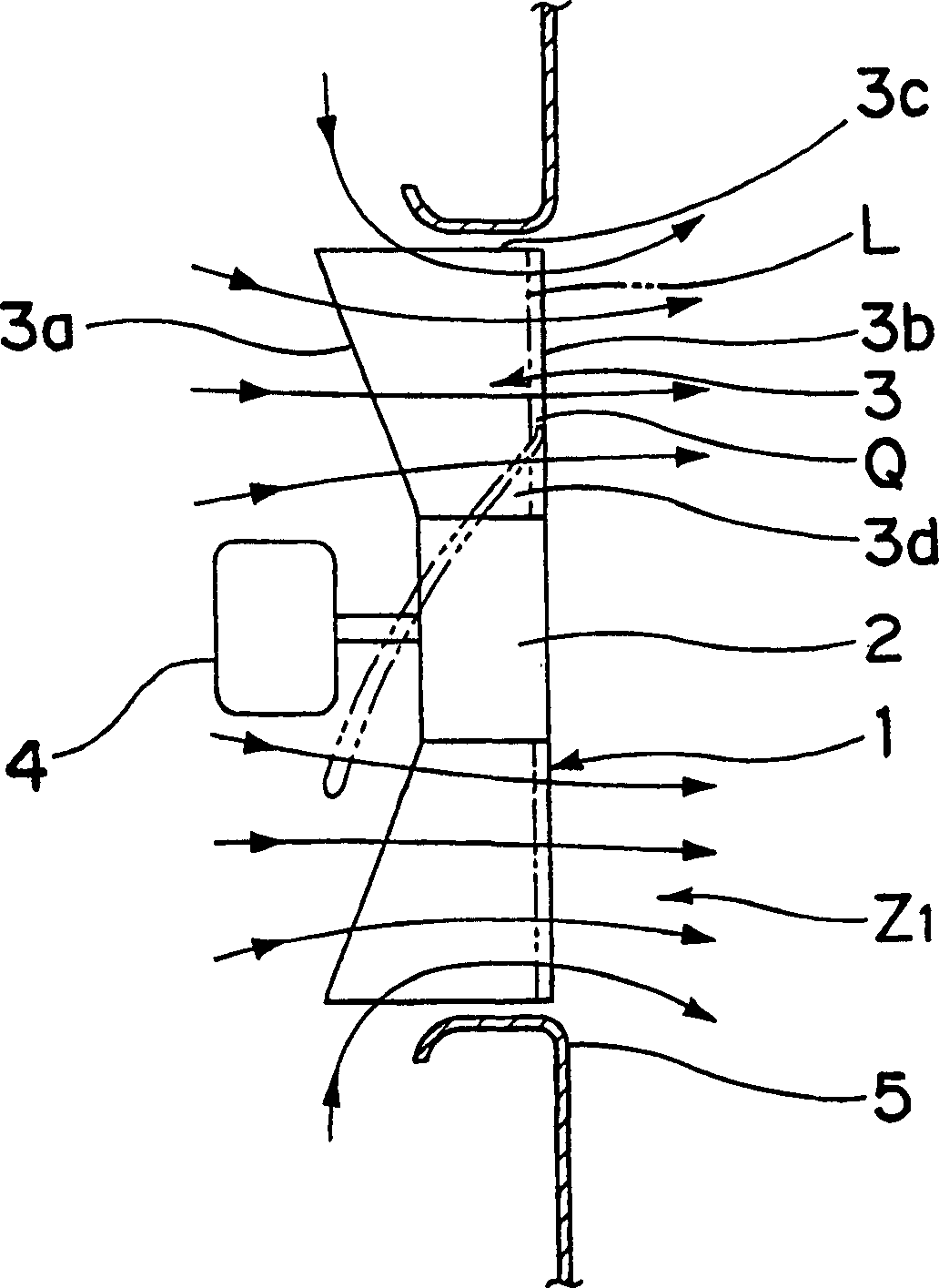
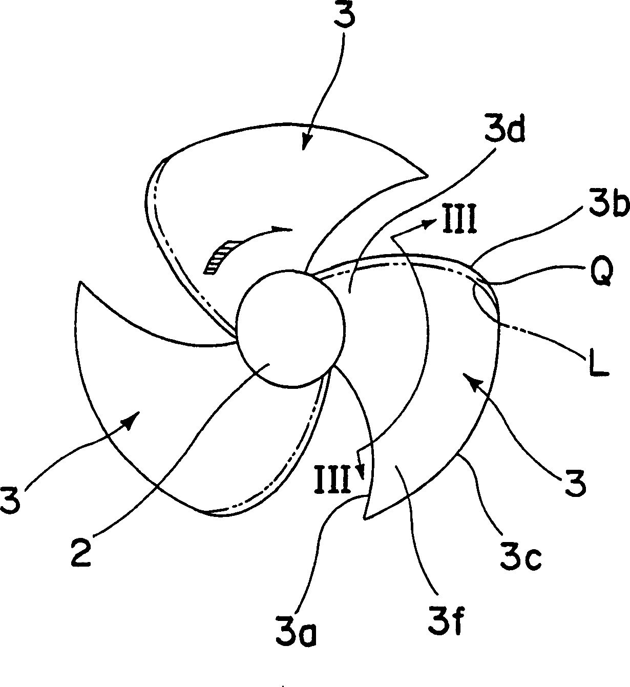
[0040] figure 1 , Shows the axial flow fan Z of the first embodiment of the present invention 1 . The axial blower Z 1 It is a so-called "propeller blower", which adopts a structure in which a plurality of (three in this embodiment) blades 3, 3, 3 are installed radially on the outer periphery of the hub 2 at a given installation angle. 1. It is driven by the motor 4 to rotate, and at the same time, on the outer peripheral side of the impeller 1, a bell cover 5 is arranged around the impeller.

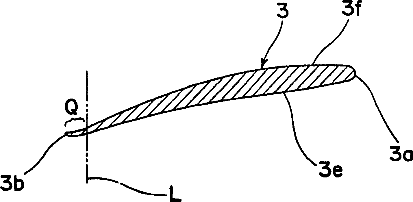
[0041] Such as figure 2 and image 3 As shown, the blade 3 of the impeller 1 is a forward-curved blade whose front edge 3a extends forward in the direction of rotation. At the same time, it has a relatively thick blade thickness an...


PUM


Abstract

A blower having an impeller (1) with a plurality of blades (3) mounted on the outer periphery of a hub (2), along the trailing edge of the blade (3) from the root (3d) of the blade to the front end (3c) of the blade (3b) A specific region (Q) extending in the spanwise direction with a given width is bent toward the negative pressure surface (3f) side. Thereby, on the negative pressure surface (3f) side of the blade (3), it is difficult for the air flow to peel off, and the wake (A 0 ) disorder. On the side of the pressure surface (3e), the flow of the airflow discharged rearward from the trailing edge (3b) is smooth, reducing turbulence. Thus reducing the wake (A 0 ), which improves the aerodynamic properties of the blade.

Description

Technical field [0001] The invention relates to a blower with an improved blade structure and an air conditioner with the blower. Background technique [0002] Figure 17 Shows the conventional axial flow blower Z 0 . The axial blower Z 0 With the following structure, the impeller 21 is driven to rotate by the motor 24. At the same time, on the outer peripheral side of the impeller 21, a bell cover 25 surrounding the impeller is arranged. The impeller 21 is arranged radially on the outer periphery of the hub 22. The blades 23, 23... are formed. In addition, such as Figure 18 and Figure 19 As shown, the blade 23 of the impeller 21 is a forward curved blade whose leading edge 23a advances forward in the direction of rotation, and is a thick-walled blade with a streamlined cross-sectional shape, and is installed at a predetermined angle with respect to the hub 22 . [0003] Such as Figure 19 As shown, the above-mentioned blade 23 has a curved form with a "camber" in the chord di...

Claims


Application Information

Patent Timeline
Patent Type & Authority Patents(China)
IPC IPC(8): F04D29/30F04D29/38F24F1/00
CPCF04D29/30F04D29/384F05D2240/304F24F1/0029
Inventor 郑志明山本治郎
Owner DAIKIN IND LTD
Why Eureka
Try Eureka