
Push-button type mechanical cipher lock heart

A technology of mechanical coded locks and keys, applied in the field of locks, can solve the problems of decreased safety, non-coded control mechanism, failure to solve lock cylinder components, etc., and achieve the effect of convenient operation and low cost

Inactive Publication Date: 2005-05-04
东莞市德福佳科技有限公司
View PDF1 Cites 0 Cited by
  • Summary
  • Abstract
  • Description
  • Claims
  • Application Information

AI Technical Summary

Problems solved by technology

[0002] In the prior art, there are two types of combination locks, electronic key combination locks and mechanical key combination locks, which fail to solve the requirement of modular design of the lock core components in technology, and the combination control mechanism is not an independent standard component, and cannot be compared with the existing ones. Some standard lock bodies and other lock components are combined to form a series of combination locks with different functions and different appearances, which is difficult to meet people's usage habits and aesthetic requirements
The disadvantage of these two types of locks is that a reset key needs to be arranged on the operating program to clear the wrong signal or give an initial working signal, which is easy to be peeped and stolen, and its safety is greatly reduced
The Chinese patent No. 95104423 discloses a combination lock. This invention adopts the technical scheme of installing magnetic pins inside the lock head, and uses the N.S poles of the magnetic pins to replace, arrange and combine words or symbols to complete the password control method. The unlocking operation The password key is required in the lock, the manufacturing process and operation of the lock are complicated, and the code cannot be freely changed, and because the password key is still required, the advantages of the combination lock cannot be displayed.

Method used


Image

  • Push-button type mechanical cipher lock heart
  • Push-button type mechanical cipher lock heart

Examples


Embodiment Construction

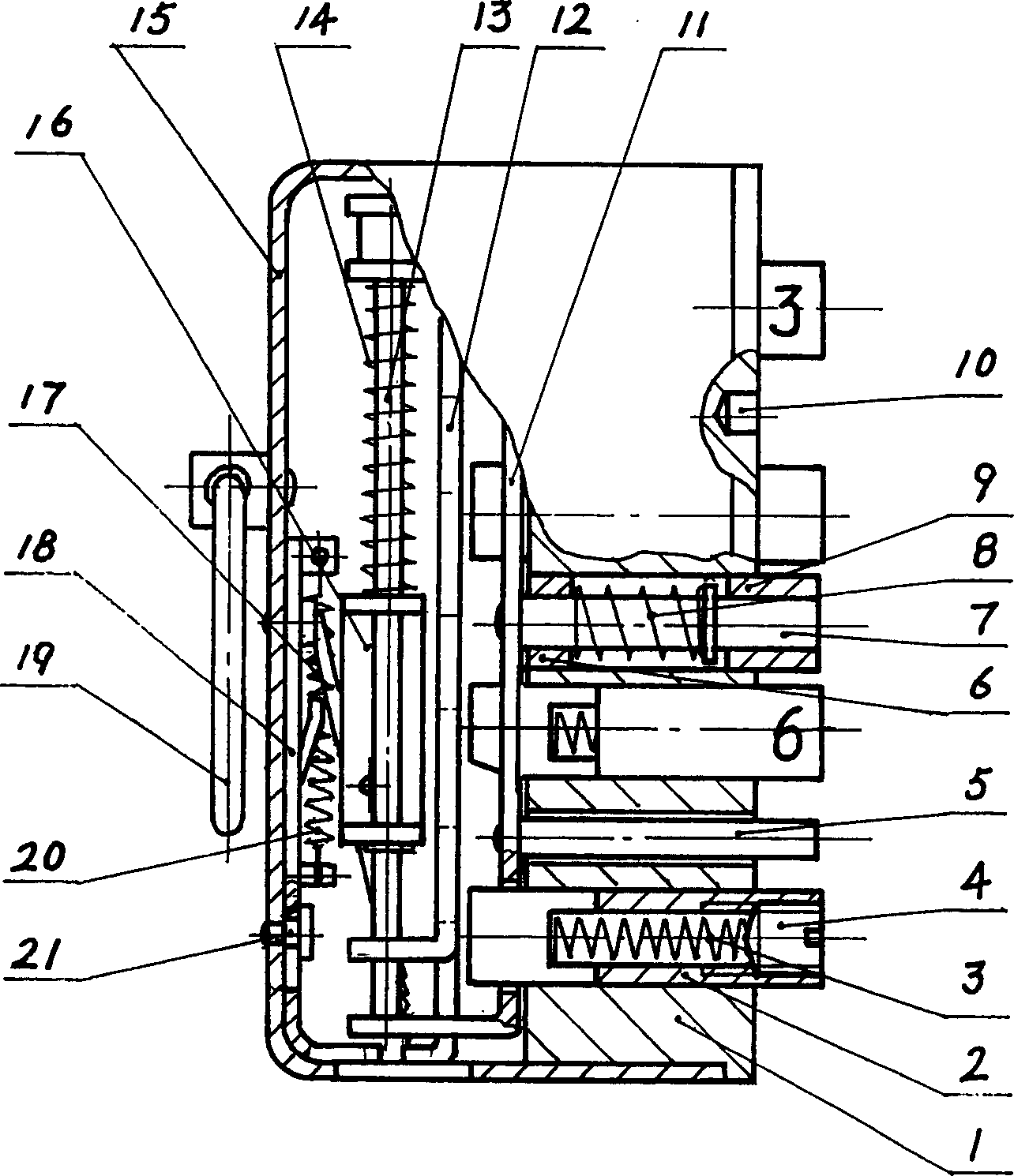
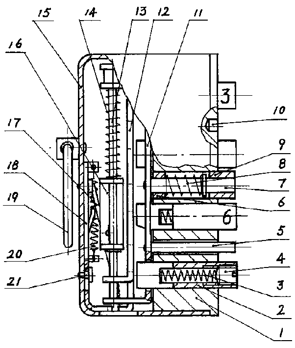
[0008] The present invention is made up of label seat 1, password key 2, push pedal 11, slide plate 12, positioning mechanism, reset sheet 18 and shell 15. The number 1 is embedded in the shell 15, the center of the push plate 11 is riveted with a guide post 7, and the surface is riveted with a limit post 5, the return spring 8 of the push plate 11 is set on the guide post 7, and the guide post 7 is inserted into the embedded In the copper sleeves 6 and 9 in the central through hole of the label base 1, it is slidingly connected with the label base 1. The two ends of the push plate 11 are vertically bent and opened to fix the guide rod 13. The guide rod 13 is equipped with a sliding connection. The slide plate 12 and its return spring 14, the positioning mechanism includes a positioning seat 16, a positioning piece 17, a torsion spring and a pin, which are sequentially set on the guide rod 13, and the reset piece 18 is fixed on the bottom of the shell 15 by a rivet 21, which ca...


PUM


Abstract

The invention discloses a push-button mechanical combination lock core, which can cooperate with existing door lock bodies and components thereof to form various push-button combination locks. The password key 2 is inserted into the label seat 1, which is a circular tubular structure with a built-in return spring 3, which is slidably connected with the label seat 1, and the middle part of the push plate 11 is riveted with a guide column 7, and the return spring 8 of the push plate 11 is set on the top, and the positioning The mechanism is composed of a positioning seat 16, a positioning piece 17, a torsion spring, and a pin, which are set on the guide rod 13. Press the password key 2 to push the real code key to slide horizontally in the label seat 1 in a preset order to complete the unlocking action; If the key is wrong, the slide plate 12 will get back to the initial position, and the reset operation will be completed, so the lock cannot be unlocked. The invention has the advantages of convenient code changing operation, automatic code destruction and reset, no password key and reset key, low cost and anti-peeping function.

Description

technical field [0001] The invention belongs to the technical field of locks, and in particular relates to a key-type mechanical coded lock cylinder whose codes are combined according to arrangement requirements and can be freely changed. Background technique [0002] In the prior art, there are two types of combination locks, electronic key combination locks and mechanical key combination locks, which fail to solve the requirement of modular design of the lock core components in technology, and the combination control mechanism is not an independent standard component, and cannot be compared with the existing ones. Some standard lock bodies and other lock components are combined to form a series of combination locks with different functions and different appearances, which is difficult to meet people's usage habits and aesthetic requirements. The shortcoming of these two types of locksets is that a reset key needs to be arranged on the operating procedure to remove wrong si...

Claims


Application Information

Patent Timeline
Patent Type & Authority Patents(China)
IPC IPC(8): E05B37/16
Inventor 连军
Owner 东莞市德福佳科技有限公司
Learn More