Energy saving multipurpose pump

A pump body and nozzle technology, applied in the field of multi-purpose pumps, can solve the problems of unsuitable use of pumps, high use cost, large energy waste, etc., and achieve the effects of low use cost, low friction resistance, and easy maintenance.

Inactive Publication Date: 2005-02-16
郑常海
View PDF1 Cites 0 Cited by
  • Summary
  • Abstract
  • Description
  • Claims
  • Application Information

AI Technical Summary

Problems solved by technology

There are large waste of energy, small displacement of the pump, and high cost of use; Chinese utility model patent ZL00203708, 4 discloses a water power machine, which uses water to drive the impeller to obtain driving force, but due to this The speed of the water power machine is low, and the existing pump is not suitable for matching use

Method used


Image

  • Energy saving multipurpose pump
  • Energy saving multipurpose pump

Examples


Embodiment Construction

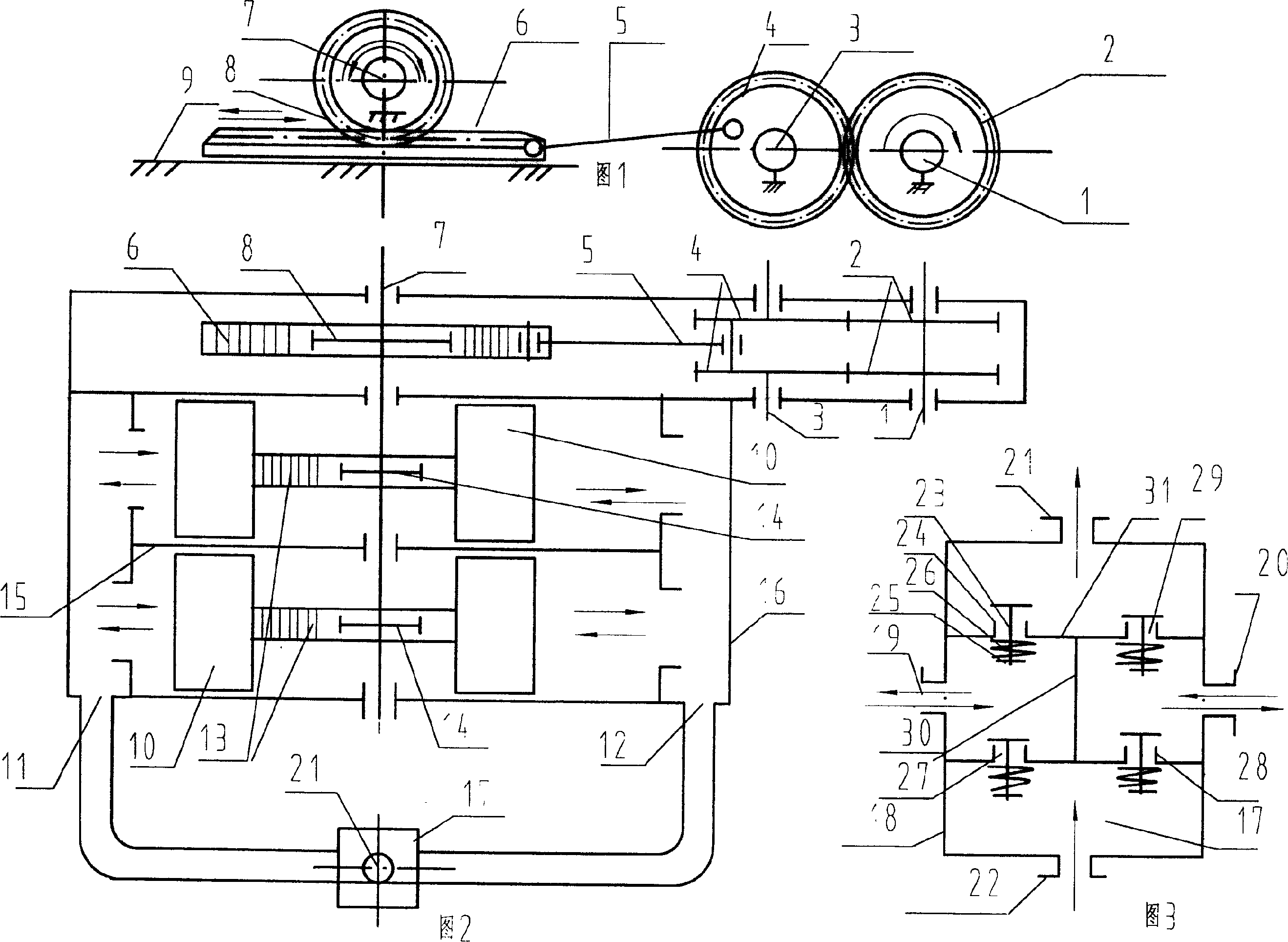
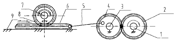
[0014] Referring to Figure 1-3, the multi-purpose pump consists of three parts: the driving device, the pump, and the one-way valve group.

[0015] The driving device is driven by a drive shaft 1, which can be driven by a low-speed motor, a hydraulic motor, a water power machine, etc., and a driving gear 2 is fixed on the drive shaft 1, and the driving gear 2 is in phase with the driven gear 4 fixed on the driven shaft 3. meshing, the main and driven gears 2 and 4 are duplex gears, the driven gear 4 is hinged with a connecting rod 5 through a pin shaft, and the connecting rod 5 is hinged with the rack 6 set on the slideway 9 through a pin shaft, The bar 6 meshes with a gear 8 fixed on the main shaft 7 .

[0016] The pump consists of a pump body 16, in which several groups of two-way pistons 10 separated by partitions 15 are built in the pump body 16. In this embodiment, there are two groups. The piston rod of the two-way piston 10 is a rack 13, which is fixed on the main shaft...


PUM


Abstract

The invented pump includes following parts and strucure. The driving gear in the driven shaft is engaged with the gear in the driven shaft, which is hinge jointed to the connecting rod. The connecting rod is hinge jointed to the rack on the slideway. The rack is engaged with the gear in the principal axis constituting the drive unit. There are several groups of two-way pistons being separated by the separator plates. The piston rods are racks, which are engaged with gear in principal axis. The internal valve body with the seprum is installed in the valve box. Multiple one way valves are installed in the internal valve body. The invention possesses the advantages of low rotate speed, large torque and output volume, low cost and energy saving. The pump can be utilized for sucking oil, irrigation by using waterpower as the source of power.

Description

technical field [0001] The invention belongs to the field of pumps and is a multipurpose pump. Background technique [0002] Existing pump structures are usually driven by motors, which require high rotational speeds to drive the pumps to work. There are large waste of energy, small displacement of the pump, and high cost of use; Chinese utility model patent ZL00203708, 4 discloses a water power machine, which uses water to drive the impeller to obtain driving force, but due to this The rotating speed of the water power machine is low, and the existing pump is not suitable for supporting use. Contents of the invention [0003] The technical problem to be solved by the present invention is to provide a multi-purpose pump with low speed, high torque, large displacement and low use cost. Especially utilizing the driving force of the water power machine, the multi-purpose pump used in conjunction with the water power machine. [0004] The technical solution adopted to solve...

Claims


Application Information

Patent Timeline
Patent Type & Authority Patents(China)
IPC IPC(8): F04B9/02
Inventor 郑常海
Owner 郑常海
Why Eureka
Try Eureka