Vacuum dust exhaust apparatus
A technology for vacuum cleaners and vacuum cleaners, which is applied in the direction of vacuum cleaners, suction filters, chemical instruments and methods, etc., which can solve the problems of larger device size and achieve the effects of small exhaust pressure loss, low energy consumption, and light weight
- Summary
- Abstract
- Description
- Claims
- Application Information
AI Technical Summary
Problems solved by technology
Method used
Image

Examples
no. 1 example
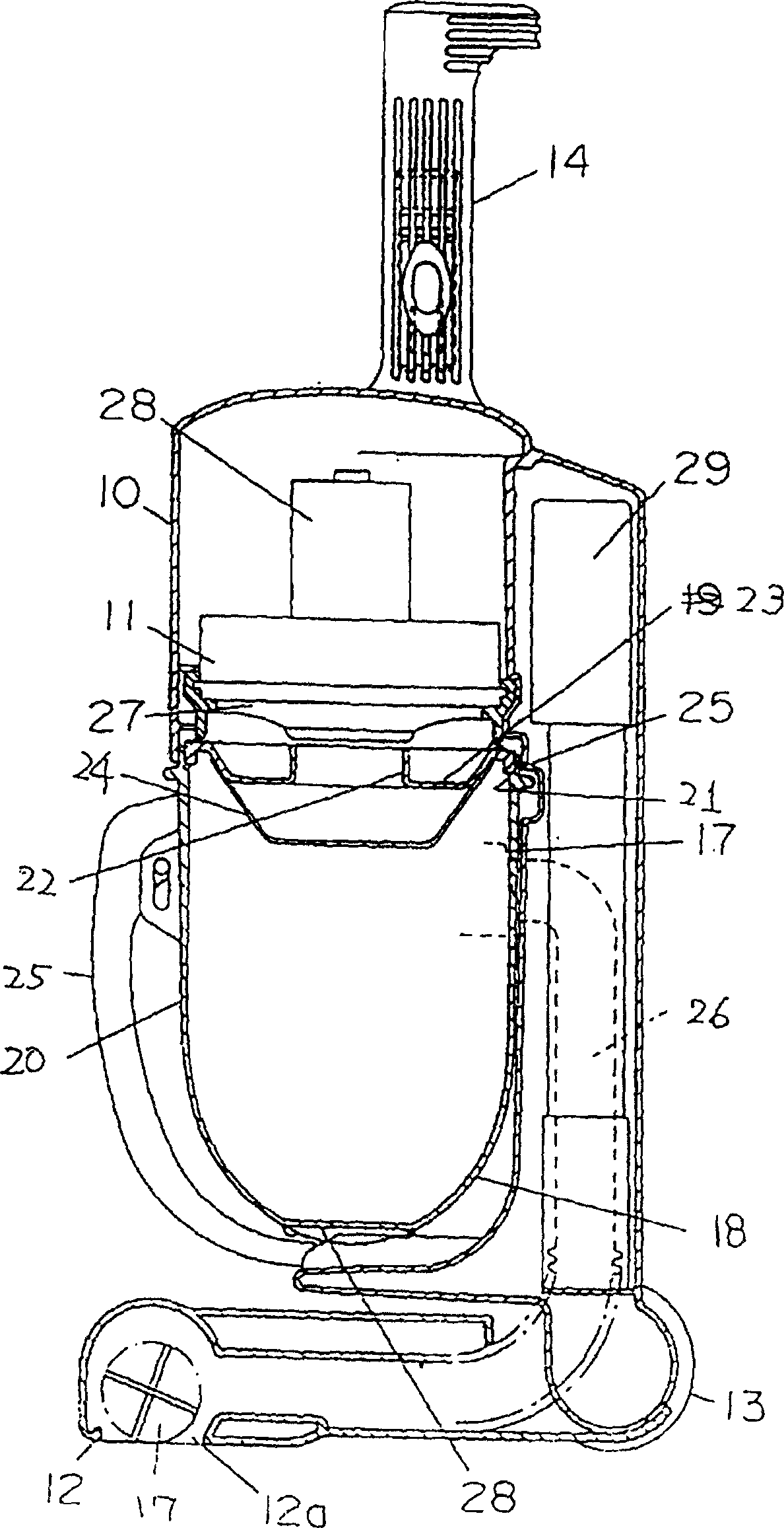
[0045] refer to Figure 1 to Figure 3 , the first embodiment of the present invention will be described below.
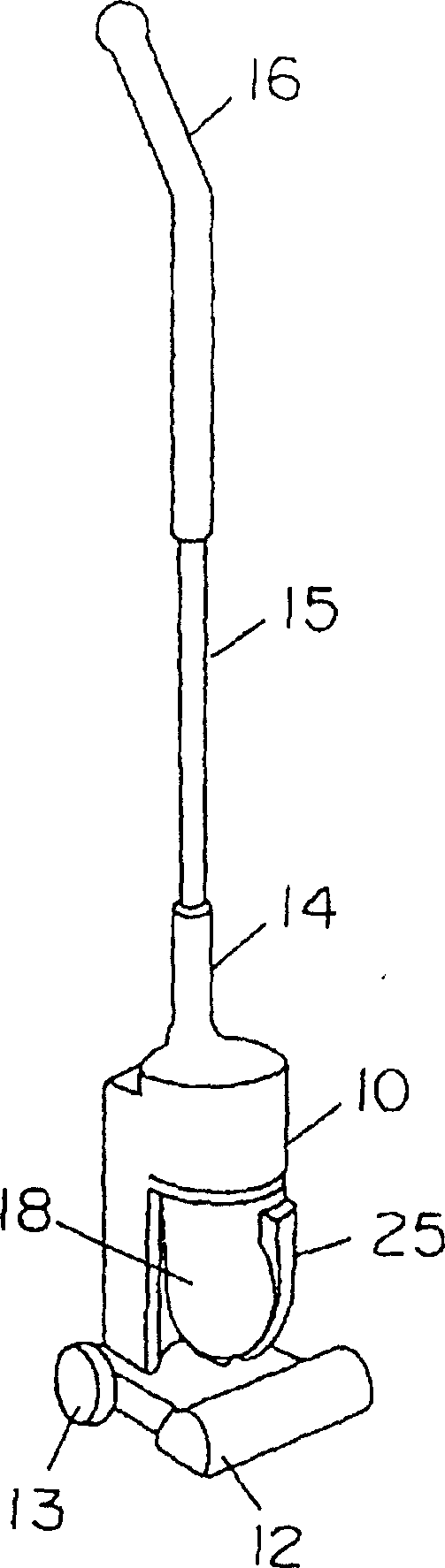
[0046] The vacuum cleaner main body 10 is equipped with an electric blower 11 that produces suction, the suction port body 12 is located at the front lower part, and the roller 13 is located at the rear lower part. The vacuum cleaner main body 10 can move on the surface to be cleaned by manipulating the handle 14 located at its upper part. In addition, by connecting the handle 16 to the handle 14 through the telescoping tube 15, the operator can operate the cleaner main body at the height of his hand.
[0047] The rolling brush 17 is located in the main body 12 of the suction port, driven by a motor or an air turbine (not shown in the figure), to collect the dust on the surface to be cleaned, and its structure makes the dust on the surface to be cleaned under the suction force of the electric blower 11 It is sucked into the suction port body 12.
[0048] Centrifug...
no. 2 example
[0071] refer to Figure 6 to Figure 8 , the second embodiment of the present invention will be described below. Incidentally, the same components as those in Embodiment 1 are denoted by the same numerals, and explanations thereof are omitted.
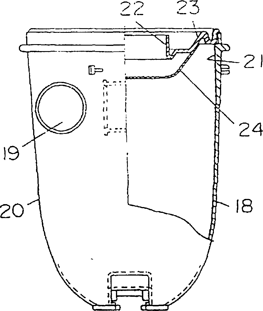
[0072] The composition of the vacuum cleaner main body 10a includes: an electric blower 11 generating suction, a suction port main body 12 located at the front lower part, and a detachable installed centrifugal force dust collecting part 18, which can make the suction when it is installed on the vacuum cleaner main body 10a The air port 19 is in pressurized contact with the suction channel 26 communicating with the suction port body 12, and is airtightly connected. An exhaust channel 30 guides part or all of the exhaust gas generated by the electric blower 11 to the main body of the suction port through the exhaust hole 31 . Other structures are the same as in Embodiment 1.
[0073] The operation of the above structure will be introd...
no. 3 example
[0079] refer to Figure 9 , the third embodiment will be introduced below. Incidentally, the same parts as those in the above-mentioned embodiments are denoted by the same numerals, and explanations thereof are omitted.
[0080] Centrifugal force dust collecting part 18 is made up of following parts: be provided with the dust box 20 of the bottom of the band of suction port 19; Cover body 23, be used for covering dust box 20 upper opening part 21, there is exhaust port 22 on the cover body 23, cover The body 23 has a filter screen 24c for covering the exhaust port 22. Other components are the same as those of the first embodiment or the second embodiment.
[0081] The operation of the above structure will be introduced below. When the centrifugal force dust collection part 18c is packed into the vacuum cleaner main body 10, the operation starts, the same as the method of the above-mentioned embodiment 1, the suction force of the electric blower 11 acts on a passage, from th...
PUM
 Abstract
Description
Claims
Application Information
 - R&D Engineer
- R&D Manager
- IP Professional
- Industry Leading Data Capabilities
- Powerful AI technology
- Patent DNA Extraction
Browse by: Latest US Patents, China's latest patents, Technical Efficacy Thesaurus, Application Domain, Technology Topic.
© 2024 PatSnap. All rights reserved.Legal|Privacy policy|Modern Slavery Act Transparency Statement|Sitemap