Combined regenerated heat energy exchanger

A heat exchanger and combined technology, applied in lighting and heating equipment, combustion methods, indirect carbon dioxide emission reduction, etc., can solve a lot of labor and other problems, and achieve the effects of saving maintenance costs, reducing lateral leakage, and reducing downtime

Inactive Publication Date: 2004-11-24
杨小明 +2
View PDF0 Cites 0 Cited by
  • Summary
  • Abstract
  • Description
  • Claims
  • Application Information

AI Technical Summary

Problems solved by technology

They are usually shipped disassembled and obtaining a fully functional system would require extensive on-site installation, as well as labor intensive

Method used


Image

  • Combined regenerated heat energy exchanger
  • Combined regenerated heat energy exchanger
  • Combined regenerated heat energy exchanger

Examples


Embodiment Construction

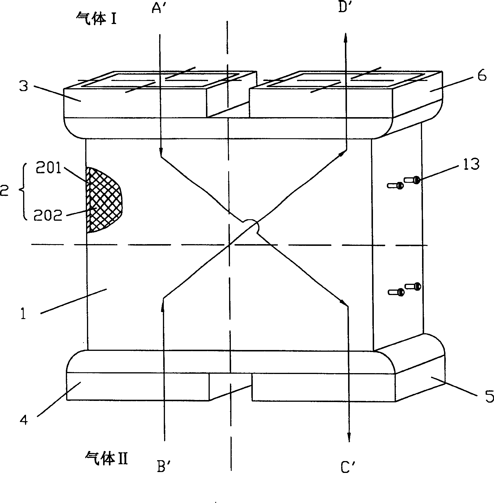
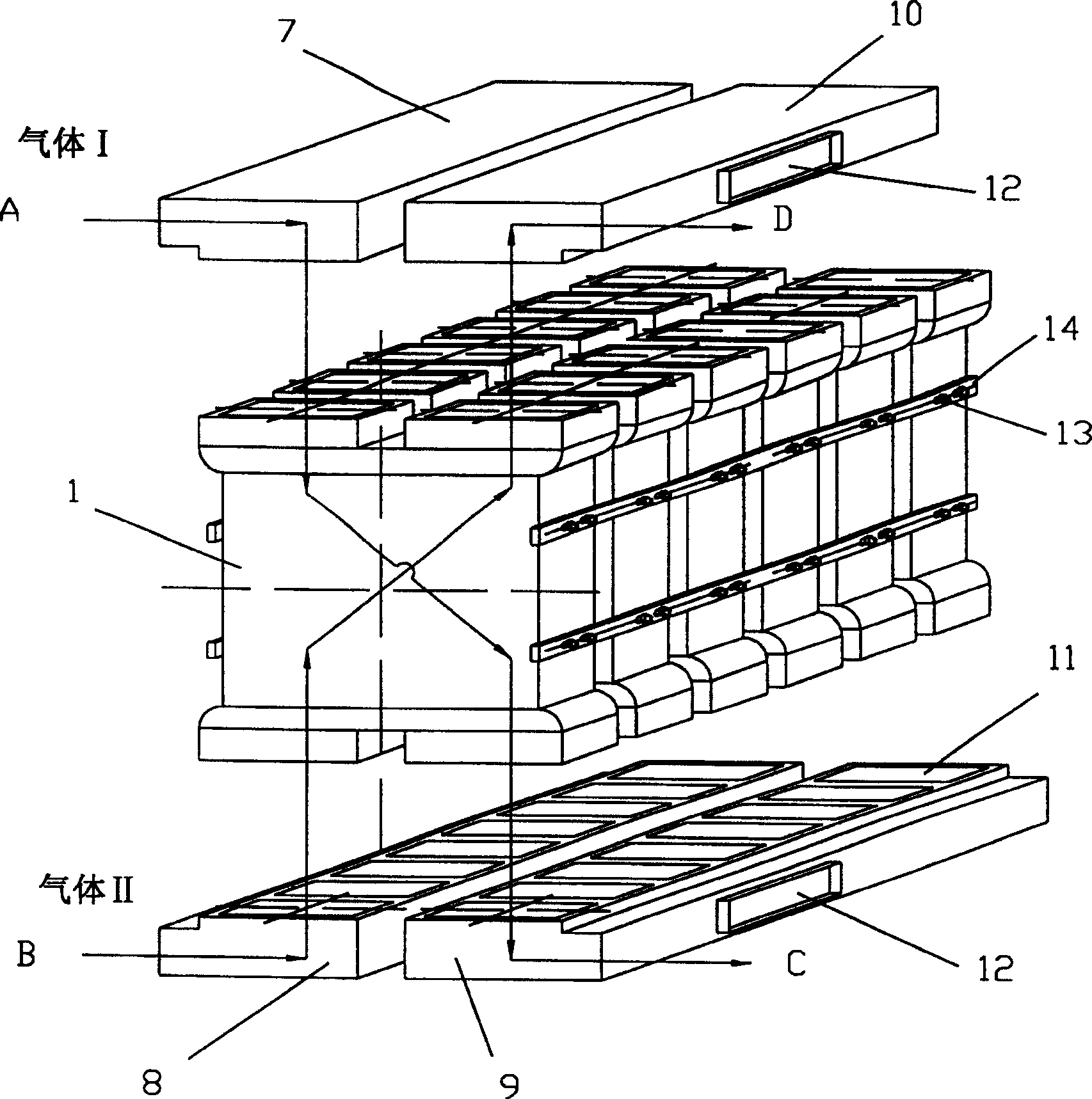
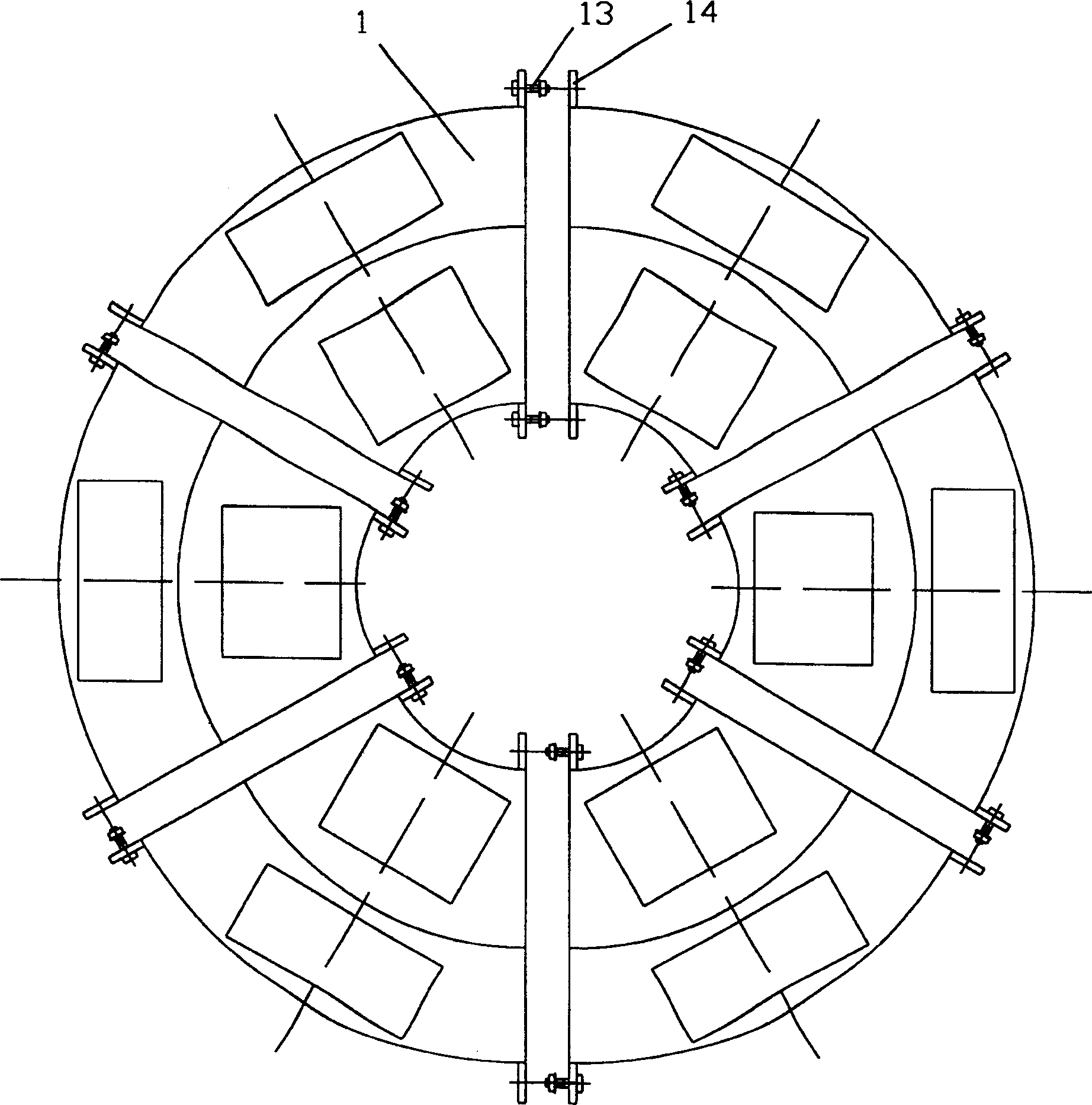
[0029] Please refer to figure 1 , figure 2 The present invention is a combined regenerative heat exchanger, which is composed of a number of mutually independent and interchangeable regenerative heat exchanger modules 1 connected to each other, and each regenerative heat exchanger module contains a packed bed 2. The shell 201 on the packed bed has four openings, and the inside of the packed bed is filled with endothermic materials 202. The openings of the packed bed are provided with inlet baffles 3, which control the flow of cold and hot gases (gas I and II). 4 and outlet baffles 5, 6. The inlet and outlet baffles 3, 4, 5, and 6 are in a sealed connection with the packed bed 2, and the gas inlet and outlet baffles 3, 4, 5, 6 and the gas inlet and outlet ducts 7, 8, 9, and 10 are sealed connections. The operation of the inlet and outlet baffles runs in sequence, so that hot gas and cold gas alternately flow through the endothermic material in the packed bed.

[0030] The inlet a...


PUM


Abstract

The combined regenerated heat energy exchanger consists of several independent and replaceable regenerated heat energy exchanging modules interconnected together. Each of the regenerated heat energy exchanging modules includes one stuffing bed comprising one casing with openings, heat absorbing material filled inside the casing, and inlet and outlet baffles, which are set at the openings to control the flow direction of both hot and cold gas and connected to the stuffing bed tightly. The inlet and outlet baffles runs in some order, so that hot gas and cold gas flow through the heat absorbing material inside the stuffing bed alternately. The modular structure makes design and manufacture economic, and result in compact structure, easy transportation, fast assembling, less gas leakage, less hot deformation, easy maintenance, low maintenance cost, etc.

Description

Technical field [0001] The invention relates to a regenerative heat energy exchanger system, in particular to a combined regenerative heat energy exchanger. Background technique [0002] The disadvantage of previous regenerative heat exchangers is that they are custom-designed as a fully integrated single monolithic structure. In power station applications, because the amount of flue gas and combustion gas is very large, the overall structure is usually very large. In this way, the regenerative heat exchanger operating in the power station cannot be transported from the manufacturer as a fully assembled whole. They are usually transported in disassembly and assembly, and obtaining a fully functional system will require a lot of on-site installation and a lot of labor. Summary of the invention [0003] The purpose of the present invention is to overcome the above shortcomings and provide an improved combined regenerative heat exchanger, which has a modular combined structure, whi...

Claims


Application Information

Patent Timeline
Patent Type & Authority Patents(China)
IPC IPC(8): F23L15/00
CPCY02E20/34
Inventor 杨小明郎果杰麦迪萨
Owner 杨小明
Why Eureka
Try Eureka