
Hand-held tool with dust extractor

A hand-held machine tool and vacuum device technology, which is applied in the direction of manufacturing tools, striking tools, light impact tools, etc., can solve the problem of plastic box clogging, and achieve the effect of avoiding dust leakage

Inactive Publication Date: 2004-11-03
ROBERT BOSCH GMBH
View PDF2 Cites 0 Cited by
  • Summary
  • Abstract
  • Description
  • Claims
  • Application Information

AI Technical Summary

Problems solved by technology

Both plastic boxes will tend to clog and can only be emptied and cleaned with significant investment

Method used


Image

  • Hand-held tool with dust extractor
  • Hand-held tool with dust extractor
  • Hand-held tool with dust extractor

Examples


Embodiment Construction

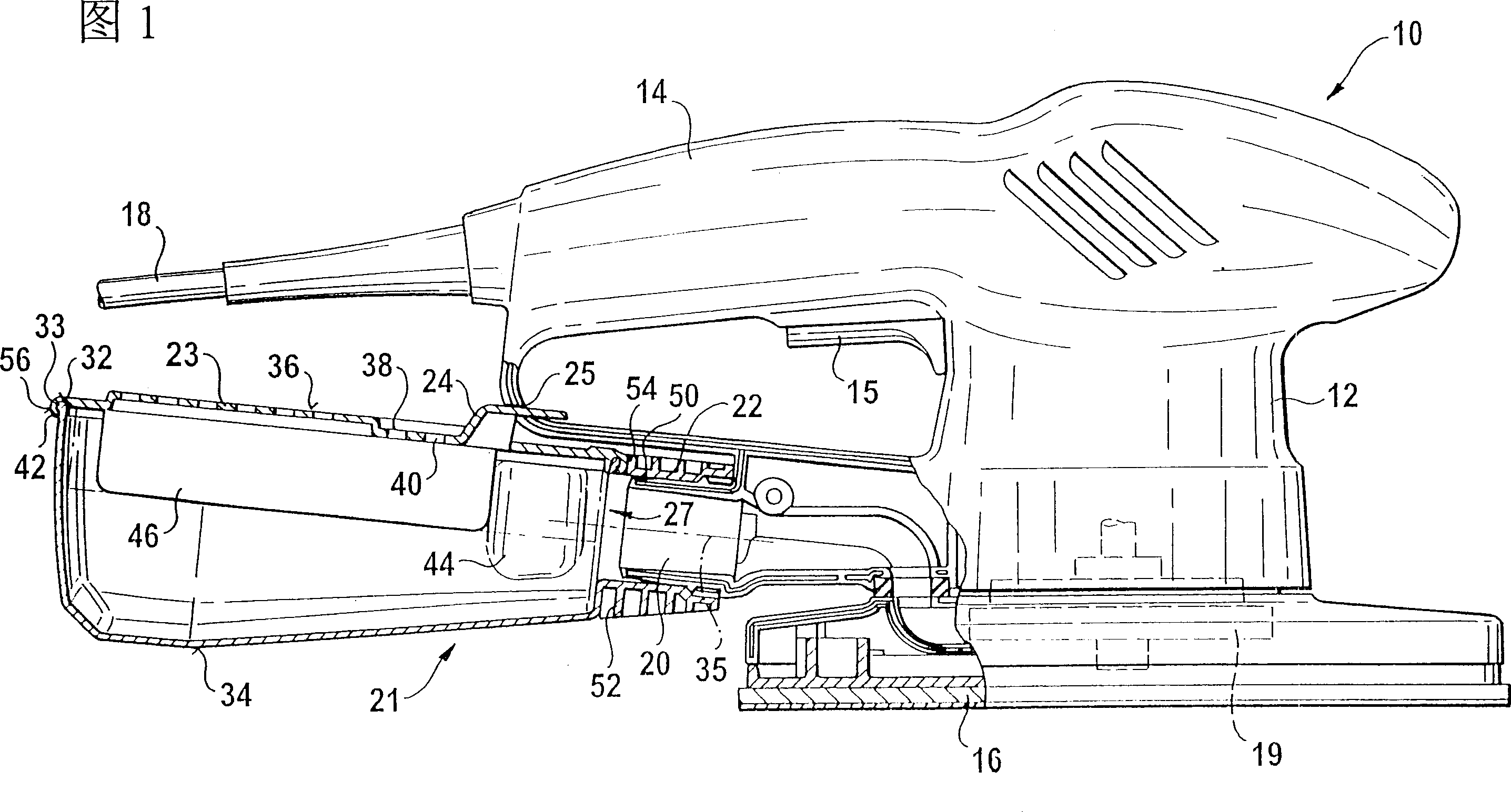
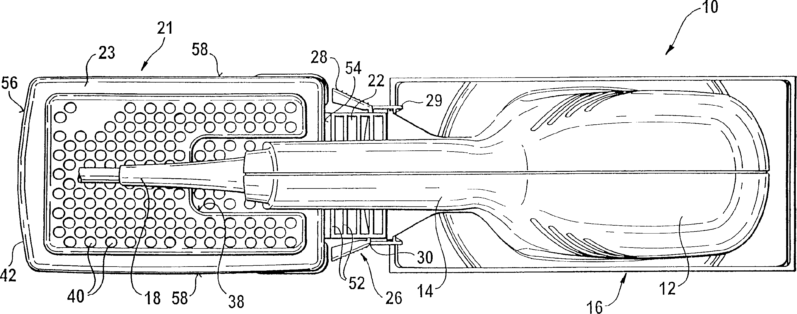
[0035] The longitudinal cross-sectional view of FIG. 1 shows a hand-held machine tool 10 constituting an ultra-finishing grinder. It has a housing 12 with a handle 14 with a switch 15 on which the structure is movably fixed Grinding plate for tool 16. The hand-held machine tool 10 has an electrical connection wire 18 at the rear end of the handle 14 and a ventilator rotor used as a dust suction device 19 inside the housing 12. The latter generates negative pressure on the grinding plate 16 when the hand-held power tool is working. As a result, the wear debris next to and below the grinding plate 16 is sucked in and blown through a discharge nozzle 20 of the housing 12.

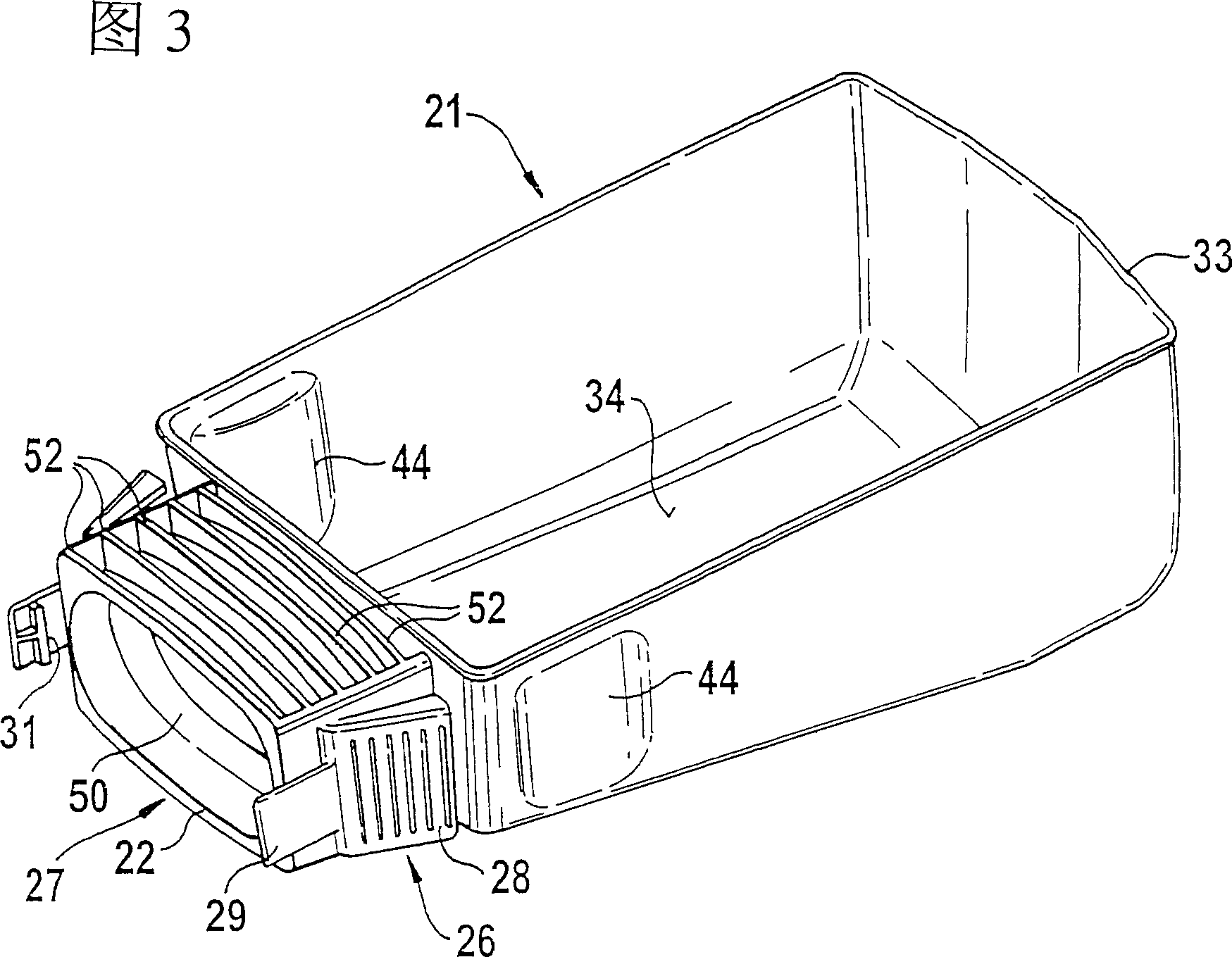
[0036] The discharge nozzle 20 carries a blow-in nozzle 22 of a cantilever-mounted dust box 21 with conformal rigidity sleeved thereon. It is airtight (up to the blowing port 27 of the blowing nozzle 22 and its upper side). The upper side of the dust box 21 is composed of a cover 23, and a hook 24 extends upward f...


PUM


Abstract

A machine (10) for a set of tools has a dust suction (19) located in its housing (12) and a outlet union (20) connected after this to which a dust box (21) for the dust collection is fastened in detachable fashion with its inlet union that is airtight on up to two sides. The top side (36) of the dust box has air exit openings (40) and on the inner side carries a dust-tight filter element (48), especially a folder filter. In the inside of the inlet union, a pair of sealing lips (500) is provided, arranged as a separate part, which is connected in one-piece fashion with closing flaps projecting into the inside of the dust box.

Description

Technical field [0001] The invention relates to a hand-held machine tool. Background technique [0002] From US 4,192,390, a percussion drill is known, which has its own vacuum cleaner, by means of which the generated drill dust (along with suction air according to the vacuum cleaner principle) can be sucked into a relatively complex dust box installed on the percussion drill, wherein Inhaled air passes through a plate-shaped filter, on which the drill dust is separated and collected in a dust box. The dust box is determined to be kept on the percussion drill and has a bottom plate that can be opened to empty the drill dust. [0003] Another percussive drill is known from US 5,467,835, which has a dust suction device with which the generated drill dust (also together with suction air according to the vacuum cleaner principle) can be sucked into a separate detachable installation on a In the dust box on the housing. A pleated filter is arranged in front of the suction port leading...

Claims


Application Information

Patent Timeline
Patent Type & Authority Patents(China)
IPC IPC(8): B25F5/00B23Q11/00
CPCB23Q11/0046Y10S55/03Y10T408/50
Inventor 多里斯·赖希斯特芬·温施安德烈亚斯·霍夫曼乌尔里希·米勒-博伊森弗朗茨·舍希阿尔克
Owner ROBERT BOSCH GMBH
Learn More