
Channel strength wrap measurement scheme

A technology of signal strength and measurement results, applied in wireless communication, transmission monitoring, electrical components, etc., can solve the problems of mobile station consumption, data loss, occupation, etc.

Inactive Publication Date: 2004-06-09
TELEFON AB LM ERICSSON (PUBL)
View PDF2 Cites 3 Cited by
  • Summary
  • Abstract
  • Description
  • Claims
  • Application Information

AI Technical Summary

Problems solved by technology

Every time the radio channel is changed, the mobile station must occupy its receiver, causing the mobile station to consume more power
In addition, because the mobile station is busy with channel reselection, data may be lost
[0016] Moreover, in some systems, there is no synchronization between the various propagations of the base station. In order to avoid additional complexity, it is hoped that the measurement of signal strength does not need to consider in which time slot the measurement is performed

Method used


Image

  • Channel strength wrap measurement scheme
  • Channel strength wrap measurement scheme
  • Channel strength wrap measurement scheme

Examples


no. 1 example

[0034] According to a first embodiment of the invention, the technique for accurately measuring the signal strengths of radio channels in the neighboring channel list consists in rotating in time the points at which signal strength measurements are made in different frames. This is shown in Figures 5a-5c , which shows an example case of rotating the signal strength measurements of the adjacent channel table during different frame periods. Such as Figure 5a As shown, the first radio channel in the adjacent channel list can be measured during measurement interval 1 at the beginning of the first frame period. Therefore, the first measurement is performed during a DCCH slot.

[0035] Such as Figure 5b As shown, the second measurement of the first radio channel may be performed at a time point, for example, 13.4 milliseconds after the start of the second frame period. Therefore, the second measurement is performed within two time slots from the first measurement, which in th...

no. 4 example

[0047] According to a fourth embodiment of the present invention, yet another technique for accurately measuring the signal strengths of the radio channels in the adjacent channel list is to perform multiple measurements for each radio channel during a frame period. This situation is shown in Figure 8 , which shows multiple signal strength measurements for each radio channel arranged within a frame period. Such as Figure 8 As shown, the four radio channels are each measured three times in a single frame period.

[0048] Such as Figure 8 As shown, the first measurement of the first radio channel in the adjacent channel list can be performed at the beginning of this frame period. This corresponds to one DCCH slot in this example. The second measurement of the first radio channel can be performed at a point in time of 0.7 milliseconds after the start of this frame period, which in this example corresponds to a DTC time slot. This makes the measured signal strength eg 2-4d...


PUM


Abstract

In a radiocommunication system including at least one base station and a mobile station connected across a first radio channel to the base station, the signal strengths of the first radio channel and neighboring radio channels are measured in the mobile station to determine whether reselection to a neighboring radio channel is necessary. Each radio channel is measured at various points in a frame period or in different frame periods, the measurements occurring in different time slots. The points at which the signal strength measurements of each radio channel are made may be rotated among the different frame periods, the measurements may be made at random points in the different frame periods, or the starting times of the measurements may be rotated among or occur randomly in the different frame periods. Alternately, the signal strengths of each radio channel may be measured at different points in a single frame period. The measurements of the signal strength of the each radio channel are averaged, and the averaged measurements are compared to determine whether reselection from the first radio channel to a neighboring radio channel is necessary.

Description

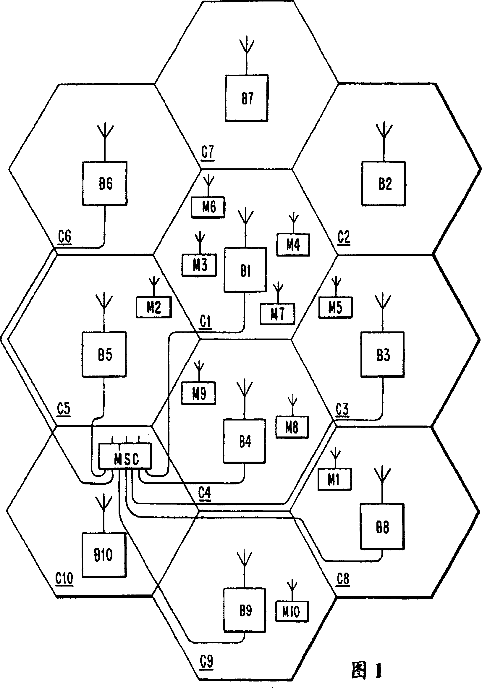
technical field [0001] The present invention relates to radio communication systems and, in particular, to techniques for measuring the signal strength of radio channels. Background technique [0002] Figure 1 shows a conventional mobile radio communication system. As can be seen from FIG. 1, the mobile radio system comprises a terrestrial system and a number of mobile stations M1-M10. The land system comprises at least one mobile services switching center MSC and a number of radio base stations B1-B10 distributed over the cells C1-C10. Each radio base station serves a respective cell by sending and receiving information from the mobile stations M1-M10 on a radio channel. Control channels are used to communicate control and overhead information between the base station and the mobile station. Each traffic channel is used to respectively support a temporary dedicated connection between a base station and a mobile station (for example to handle a voice call). A mobile serv...

Claims


Application Information

Patent Timeline
IPC IPC(8): H04B17/00H04W36/08H04W48/16
CPCH04W48/16H04W36/0094H04B17/0077H04W36/30H04B17/382H04W36/302
Inventor C·B·托特K·W·安德森
Owner TELEFON AB LM ERICSSON (PUBL)
Learn More