Battery transportation and storage device and storage method
A storage device and battery technology, applied in the directions of transportation and packaging, packaging, packaging item types, etc., can solve the problem of poor battery transportation effect, etc., and achieve the effect of good fixing effect, avoiding collision, and enhancing service life.
- Summary
- Abstract
- Description
- Claims
- Application Information
AI Technical Summary
Problems solved by technology
Method used
Image
Examples
Embodiment 1
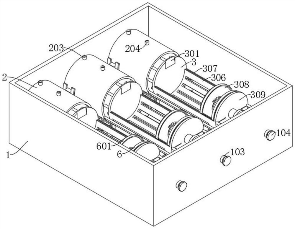
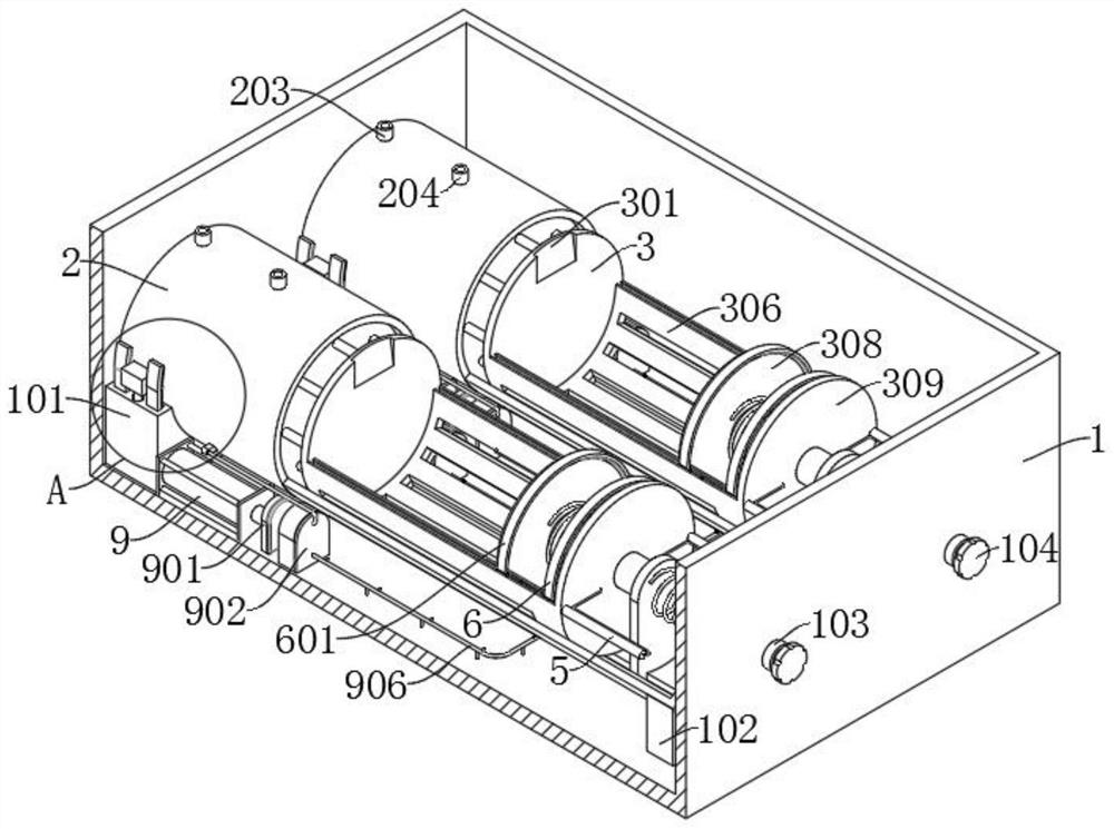
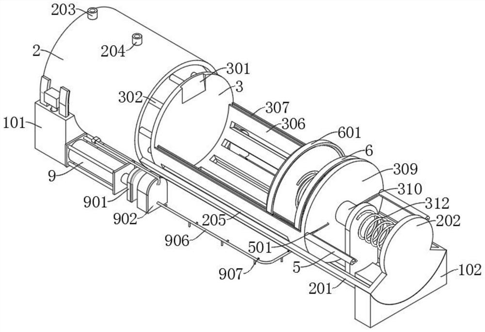
[0055] refer to Figure 1-Figure 10 and Figure 13 , a battery transportation and storage device, comprising a box body 1, and further comprising: a first fixing seat 101 and a second fixing seat 102 fixedly connected to the inner wall of the box body 1, and a cylinder body 2 is placed on the first fixing seat 101, The outer wall of the cylinder body 2 is provided with a first circular arc plate 201, the end of the first circular arc plate 201 away from the cylinder body 2 is provided with a first end plate 202, and the end of the first circular arc plate 201 close to the first end plate 202 is placed on the On the second fixed seat 102 , the cylinder body 2 is provided with a first one-way valve 203 and a second one-way valve 204 , and also includes a fixed plate 3 slidably connected to the first arc plate 201 and a fixed plate 3 slidably connected to the cylinder body 2 Inside the first piston plate 303 and the second piston plate 305, the first piston plate 303 is placed b...
Embodiment 2
[0061] refer to Figure 1-Figure 9 and Figure 14 , a battery transportation and storage device, which is basically the same as Embodiment 1. Further, the outer wall of the second end plate 309 is provided with a first gas cylinder 4, and a third piston plate 401 is slidably connected in the first gas cylinder 4. The outer wall of the piston plate 401 is fixedly connected with a first push rod 402, the sliding plate 308 is fixedly connected with the first push rod 402, a second spring 403 is arranged between the sliding plate 308 and the first air cylinder 4, and the second spring 403 is sleeved on the first push rod 402. The outer wall of the first push rod 402 .
[0062] The outer wall of the second end plate 309 is provided with a second air cylinder 5 , a connecting pipe 501 is connected between the second air cylinder 5 and the first air cylinder 4 , the second circular arc plate 306 is provided with a T-shaped groove 307 , and the first semicircular rod 6 The T-shaped ...
Embodiment 3
[0069] refer to Figure 2-Figure 4 , Figure 10-Figure 13 and Figure 15 , a battery transportation and storage device, which is basically the same as Embodiment 2. Further, the outer wall of the cylinder body 2 is provided with a square tube 7, the bottom of the square tube 7 is provided with an intubation tube 701, and the first fixing seat 101 is provided with a The jack 105 matched with the cannula 701, the jack 105 is provided with an inner pipe 106, the inner wall of the cannula 701 is fixedly connected with a support plate 702, the support plate 702 is provided with a through hole 703, and the cannula 701 is slidably connected with a support plate 702. A stopper 704, the stopper 704 is arranged below the support plate 702, a fifth spring 705 is arranged between the support plate 702 and the stopper 704, the stopper 704 is provided with a tapered hole 707, and the bottom of the support plate 702 is fixedly connected with a plug Rod 706, the bottom of the insertion rod ...
PUM
 Abstract
Description
Claims
Application Information
 - R&D
- Intellectual Property
- Life Sciences
- Materials
- Tech Scout
- Unparalleled Data Quality
- Higher Quality Content
- 60% Fewer Hallucinations
Browse by: Latest US Patents, China's latest patents, Technical Efficacy Thesaurus, Application Domain, Technology Topic, Popular Technical Reports.
© 2025 PatSnap. All rights reserved.Legal|Privacy policy|Modern Slavery Act Transparency Statement|Sitemap|About US| Contact US: help@patsnap.com


