


Quick Research
Generate reliable direction feasibility study reports for your R&D in just a few steps.

Technical Q&A
Discover and master advanced knowledge NOW. Basics, ideas, possibilities, all at once.

Find Solutions
As an expert in R&D theories, this can generate solutions to your technical problems instantly.

Evaluate Feasibility
Analyze your overall solution with one click, know your potential R&D risks in advance.

Monitor Landscape
Get weekly tech updates, stay abreast of the latest tech innovations and key insights.
Motor equipment performance testing device
A technology for testing devices and motor equipment, which is applied in the direction of motor generator testing, measuring devices, measuring device casings, etc. It can solve problems such as cumbersome process, single motor load form, and reduce the speed of the test motor to achieve the effect of increasing running resistance
- Summary
- Abstract
- Description
- Claims
- Application Information
AI Technical Summary
Problems solved by technology
Method used
Image

Examples
Embodiment 1
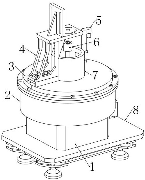
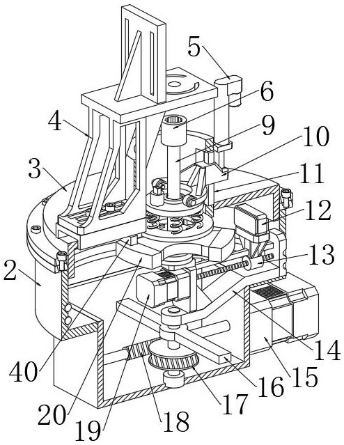
[0033] Refer to the attached Figure 1-8, a performance testing device for electrical equipment, comprising a base 8, a speed sensor 40, a vibration sensor 26, a pressure sensor 29, an electromagnet 12, a casing 1, a casing 2 and a cover plate 3, and the center of the upper end of the cover plate 3 passes through a circular opening A sleeve 7 is fixedly connected, and a load mechanism is connected in the sleeve 7. The load mechanism is used to connect to the output shaft of the motor to be tested to provide a load force. A rotating shaft is vertically arranged in the casing 1, and a transmission is connected to the shaft wall of the rotating shaft. Mechanism, the transmission mechanism is connected with the electromagnet 12, which is used to change the force of the electromagnet 12 on the load mechanism, so that the load mechanism can generate different vibration forces. The receiving end device is connected to the receiving end device, and the receiving end device displays an...
Embodiment 2
[0036] Embodiment 2: What is different based on Embodiment 1 is;
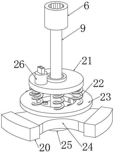
[0037] Refer to the attached Figure 4-5 , The load mechanism includes a main shaft 9, the upper end of the main shaft 9 is fixedly connected with a coupling 6, and the connecting shaft 6 adopts a retractable spline gauge and a spline shaft to connect the output shaft of the motor to be tested and the main shaft 9, and the spline shaft and the spline shaft are connected. The fitting clearance of the gauge is 0.01-0.03 mm, and it is fixed with symmetrically arranged screws to ensure the connection rigidity of the main shaft 9 and the shaft of the motor to be tested. When performing the locked-rotor torque test, it is only necessary to turn off the power of the motor to be tested and loosen the screws. After that, the power supply can be turned on again, the lower end of the main shaft 9 is fixedly connected with a rotor 24, a plurality of uniformly distributed permanent magnets 20 are fixedly connected to the ro...
Embodiment 3
[0041] Embodiment 3: The difference based on Embodiment 1 is;
[0042] Refer to the attached figure 2 and Image 6 , the transmission mechanism includes a curved rod 14, one end of the curved rod 14 is fixed on the upper end of the rotating shaft, the lower end of the rotating shaft is rotatably connected to the inner wall of the casing 1 through a rolling bearing, and the casing 1 is fixedly connected with a crossbar 16, the rod wall of the crossbar 16 A worm wheel 17 is fixedly connected to the shaft wall of the rotating shaft through a ball bearing. A worm 18 is engaged with one side of the worm wheel 17, and a first motor 15 is fixedly connected to one side of the housing 1. The first motor The output end of 15 penetrates the side wall of the housing 1 and is fixedly connected with one end of the worm 18. The rod wall of the bending rod 14 is fixedly connected with a fixing frame 30, and the fixing frame 30 is connected with an adjusting unit, and the adjusting unit is c...
PUM
 Abstract
Description
Claims
Application Information
 - R&D Engineer
- R&D Manager
- IP Professional
- Industry Leading Data Capabilities
- Powerful AI technology
- Patent DNA Extraction
Browse by: Latest US Patents, China's latest patents, Technical Efficacy Thesaurus, Application Domain, Technology Topic, Popular Technical Reports.
© 2024 PatSnap. All rights reserved.Legal|Privacy policy|Modern Slavery Act Transparency Statement|Sitemap|About US| Contact US: help@patsnap.com