
Engineering machinery gearbox output shaft assembly and adjusting method

A technology for output shaft assembly and construction machinery, which is applied in the direction of mechanical equipment, mechanical control devices, transmission boxes, etc., and can solve the problems of gear disengagement, accelerated tooth wear, and fracture, etc.

Pending Publication Date: 2022-08-05
龙工(福建)桥箱有限公司
View PDF0 Cites 0 Cited by
  • Summary
  • Abstract
  • Description
  • Claims
  • Application Information

AI Technical Summary

Problems solved by technology

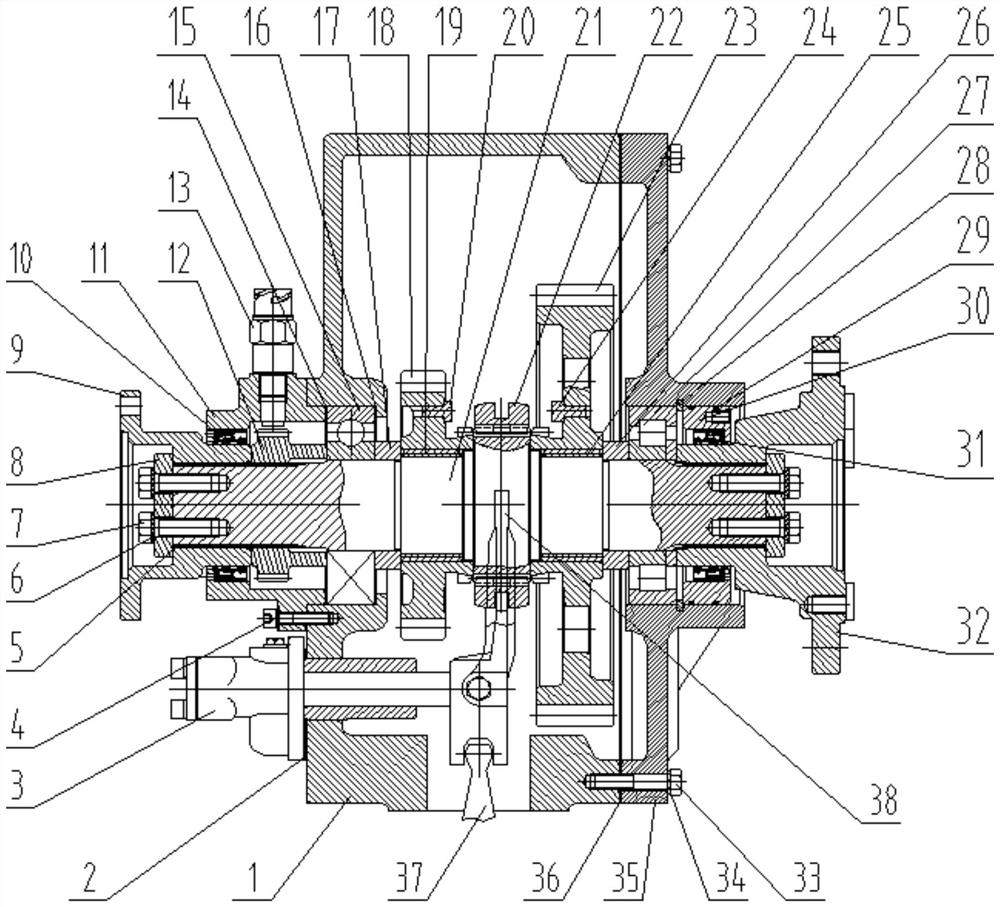
[0006] The purpose of the present invention is to provide a construction machinery gearbox output shaft assembly and adjustment method with simple and compact structure, long service life and convenient maintenance, so as to solve the problem of interference between the fork head of the shift fork and the annular groove of the sliding gear sleeve in the prior art. Causes wear and tear to damage the shift fork and the lack of engagement length of the engaging teeth when shifting gears can easily lead to gear disengagement and accelerated tooth wear or even breakage

Method used


Image

  • Engineering machinery gearbox output shaft assembly and adjusting method
  • Engineering machinery gearbox output shaft assembly and adjusting method
  • Engineering machinery gearbox output shaft assembly and adjusting method

Examples


Embodiment 1

[0038] The adjustment method is as follows:

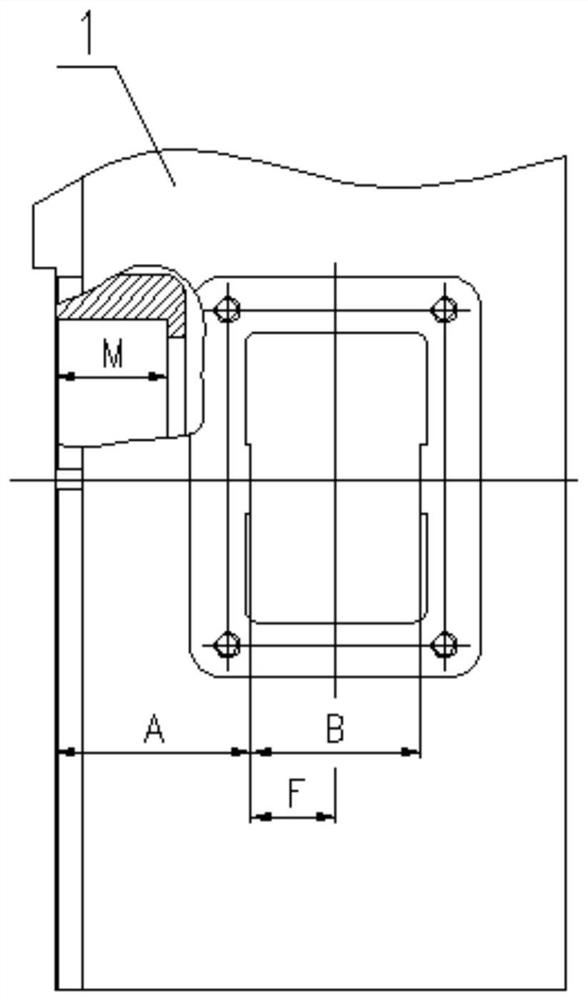
[0039] S1: The distance from the left limit surface of the window of box 1 to the installation surface of shift fork assembly 3 is A=78.86mm;

[0040] S2: The distance between the two limit surfaces of the measurement box 1 window is B=67.98mm;

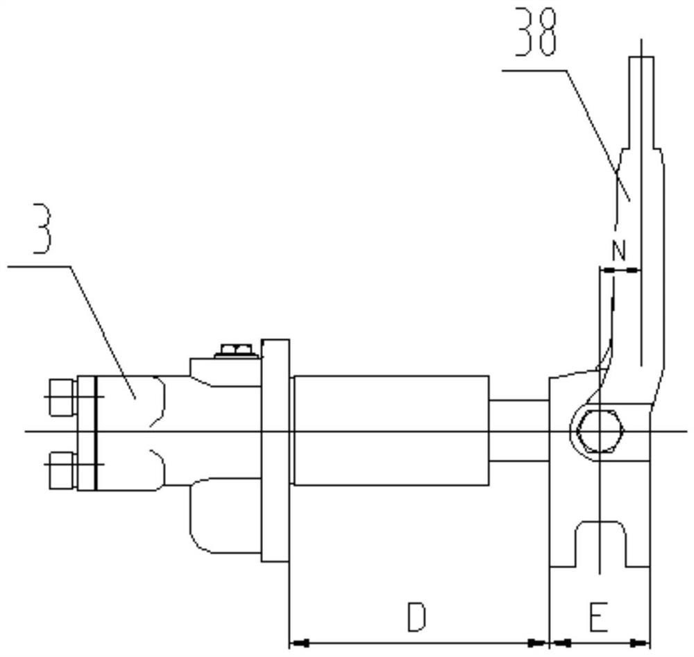
[0041] S3: Adjust the shift fork 38 of the shift fork assembly 3 to the neutral position, and measure the distance from the end face of the shift fork bracket in the shift fork assembly 3 to the limit surface on the left side of the shift fork 38 as D=94.62 mm;

[0042] S4: Measure the thickness of the two outer limit surfaces of the U-shaped head of the shift fork 38 to be E=37.06mm;

[0043] S5: Calculate the distance from the two outer sides of the U-shaped head of the shift fork 38 to the left and right limit surfaces of the box 1 window as F=(B-E) / 2=15.46mm;

[0044] S6: The shift fork 38 is adjusted to the center of the two limit planes of the window of the box body 1: the thickne...

Embodiment 2

[0052] The adjustment method is as follows:

[0053] S1: The distance from the left limit surface of the window of box 1 to the installation surface of shift fork assembly 3 is A=78.92mm;

[0054] S2: The distance between the two limit surfaces of the measurement box 1 window is B=68.06mm;

[0055] S3: Adjust the shift fork 38 of the shift fork assembly 3 to the neutral position, and measure the distance from the end face of the shift fork bracket in the shift fork assembly 3 to the limit surface on the left side of the shift fork 38 as D=94.96 mm;

[0056] S4: Measure the thickness of the two outer limit surfaces of the U-shaped head of the shift fork 38 to be E=36.98mm;

[0057] S5: Calculate the distance from the two outer sides of the U-shaped head of the shift fork 38 to the left and right limit surfaces of the box 1 window as F=(B-E) / 2=15.54mm;

[0058] S6: The shift fork 38 is adjusted to the center of the two limit planes of the window of the box body 1: the thickne...


PUM

PropertyMeasurementUnit
Thicknessaaaaaaaaaa
Thicknessaaaaaaaaaa

Abstract

The invention discloses an output shaft assembly of an engineering machinery gearbox. Comprising a box body, a shifting fork adjusting gasket, a shifting fork assembly, a first sealing ring, a lock washer, a shaft end baffle, a rear flange, a first combined oil seal, a rear oil seal seat, a speed measuring gear, a rotating speed sensor, a first output shaft adjusting gasket, a first bearing, a second output shaft adjusting gasket, a left spacer bush, a high-speed gear, a first sliding bearing, a first limiting pin, an output shaft, a sliding gear sleeve and a low-speed gear. A second limiting pin, a second sliding bearing, a right spacer bush, a second bearing, a check ring, a second sealing ring, a front oil seal seat, a second combined oil seal, a front flange, a bolt, a spring washer, a box cover and a sealing gasket are included. Adjustment of the output shaft assembly comprises centering adjustment of the gear shifting fork and two limiting faces of a box window, the center line of the sliding gear sleeve and the center of a fork head of the gear shifting fork. The problems that the shifting fork is abraded and damaged due to interference of the shifting fork head and the annular groove of the sliding gear sleeve, and gear disengagement and tooth abrasion are caused due to the fact that the joint length of the joint teeth is insufficient in the gear shifting process are solved.

Description

technical field [0001] The invention relates to the technical field of construction machinery gearbox equipment, in particular to a construction machinery gearbox output shaft assembly and an adjustment method. Background technique [0002] The gearbox is one of the core components of construction machinery, especially loaders. It can change the transmission ratio and expand the range of torque and rotational speed of the driving wheel to adapt to frequently changing working conditions. In addition, when the rotation direction of the engine remains unchanged, the loader can achieve forward, neutral and reverse gear switching and power output. The output shaft assembly is the main power output device and the main component for outputting power. [0003] The sliding gear sleeve of the existing construction machinery output shaft assembly is installed on the fork head of the shift fork through an annular groove in the middle. Engage to achieve forward, neutral and reverse gear...

Claims


Application Information

Patent Timeline
IPC IPC(8): F16H57/023F16H57/02F16H63/32F16H57/029F16H57/021
CPCF16H57/023F16H57/02F16H63/32F16H57/029F16H57/021F16H2063/322
Inventor 阙智坚任高奇陈其春邓正斌谢鹏
Owner 龙工(福建)桥箱有限公司
Learn More