


Quick Research
Generate reliable direction feasibility study reports for your R&D in just a few steps.

Technical Q&A
Discover and master advanced knowledge NOW. Basics, ideas, possibilities, all at once.

Find Solutions
As an expert in R&D theories, this can generate solutions to your technical problems instantly.

Evaluate Feasibility
Analyze your overall solution with one click, know your potential R&D risks in advance.

Monitor Landscape
Get weekly tech updates, stay abreast of the latest tech innovations and key insights.
Garbage processor and control method thereof
A technology of garbage disposer and control method, which is applied in the direction of instruments, scientific instruments, buildings, etc., which can solve the problems of easy deposition and blockage of kitchen waste, and achieve the effect of simple and flexible switching method and reliable connection
- Summary
- Abstract
- Description
- Claims
- Application Information
AI Technical Summary
Problems solved by technology
Method used
Image

Examples
Embodiment 1
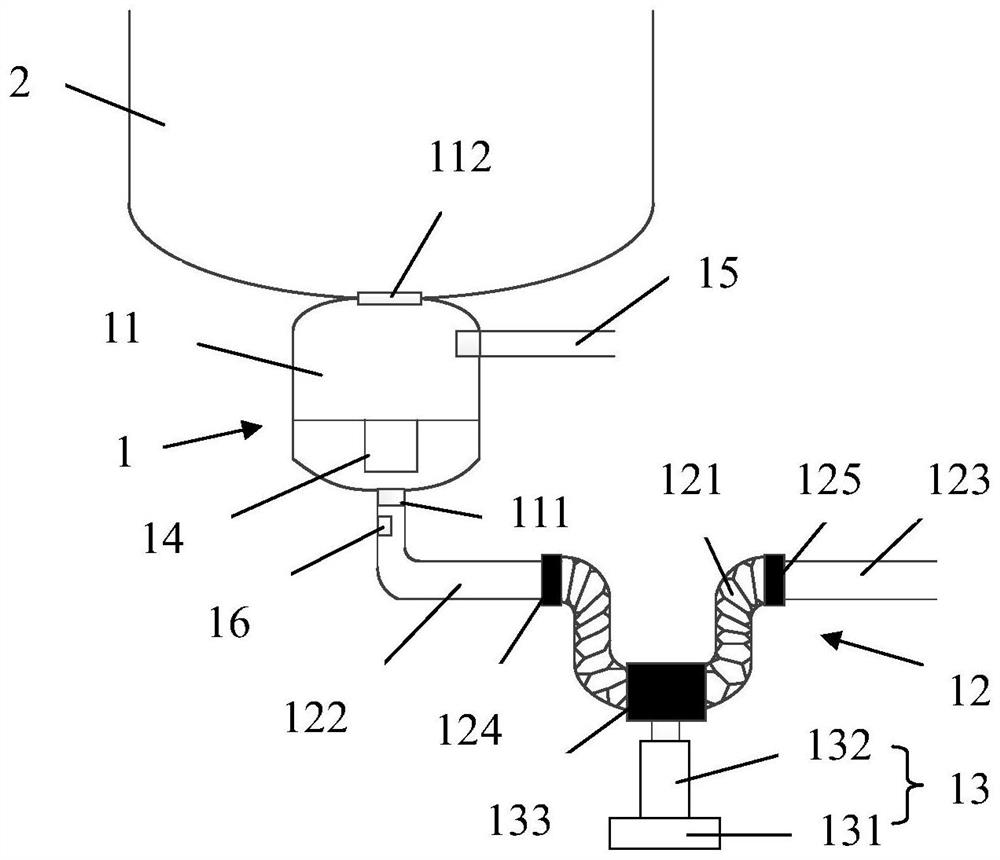
[0055] like figure 1 and figure 2 As shown, this embodiment provides a garbage disposer 1, including a garbage disposal cavity 11, a downpipe 12 and a drive mechanism 13, the bottom of the garbage disposal cavity 11 has a garbage outlet 111, and the top of the garbage disposal 1 has a garbage outlet 111. There is a garbage inlet 112 suitable for connecting with the water outlet of the water tank 2. The kitchen waste in the water tank 2 can enter the garbage disposal cavity 11 through the water outlet and the garbage inlet 112, and be ground and pulverized by the grinding component and then discharged. to the sewer pipe 12.
[0056] Further, the sewer pipe 12 is connected to the garbage outlet 111, one end of the sewer pipe 12 is connected to the garbage outlet 111, and the other end is connected to the external sewer pipe, which is suitable for discharging the ground kitchen waste to Urban sewage recycling system.
[0057] In this embodiment, the downpipe 12 includes at le...
Embodiment 2
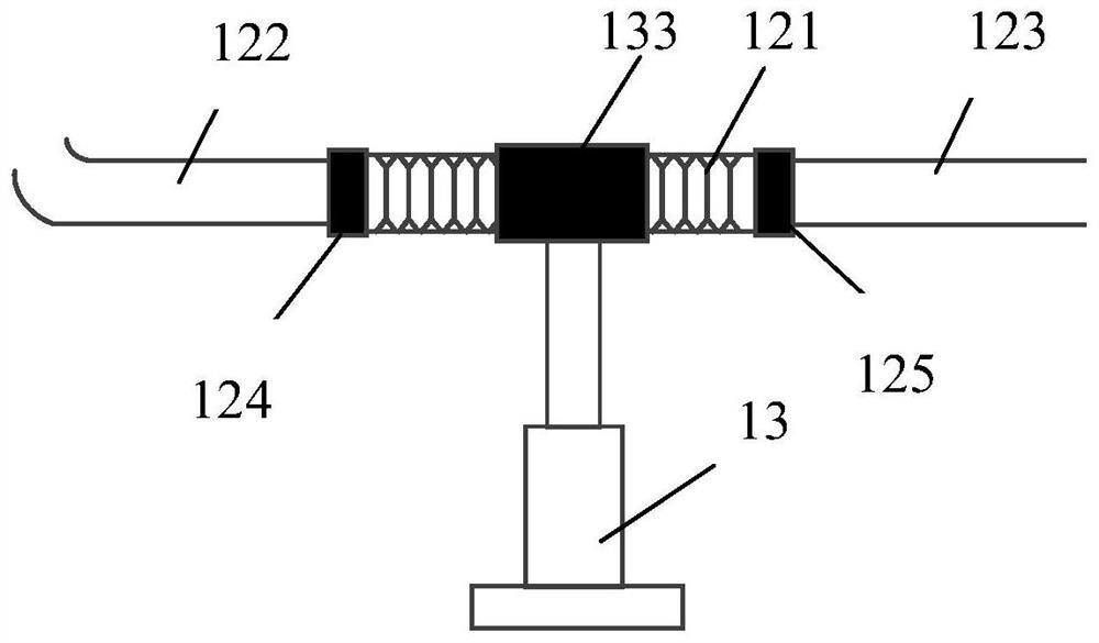
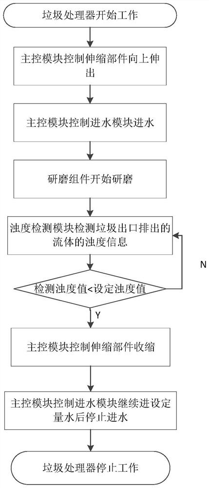
[0082] like Figure 1 to Figure 3 As shown, this embodiment also provides a control method for a garbage disposer, which is applied to the garbage disposer 1 of the first embodiment. The control method includes the following steps: when the garbage disposer 1 starts to work, the driving mechanism 13 The hose 121 is controlled to switch from the first U-shaped state to the second straight state.
[0083] The above-mentioned control method of the garbage disposer provided in this embodiment is mainly aimed at the problem that the garbage discharged after the garbage disposer 1 is processed is easily deposited at the bottom of the U-shaped sewer pipe 12 and causes blockage. The hose 121 is released so that the hose 121 is switched from the U-shaped to the straight-shaped, thereby effectively preventing the clogging caused by the accumulation of garbage at the bottom of the U-shaped tube.
[0084] Optionally, combine figure 2 and image 3 As shown, the control method further i...
PUM
 Abstract
Description
Claims
Application Information
 - R&D Engineer
- R&D Manager
- IP Professional
- Industry Leading Data Capabilities
- Powerful AI technology
- Patent DNA Extraction
Browse by: Latest US Patents, China's latest patents, Technical Efficacy Thesaurus, Application Domain, Technology Topic, Popular Technical Reports.
© 2024 PatSnap. All rights reserved.Legal|Privacy policy|Modern Slavery Act Transparency Statement|Sitemap|About US| Contact US: help@patsnap.com