
Clamping device for flexibly clamping and detecting rotary motor support assembly workpiece

A motor bracket and clamping device technology, which is applied in the field of aerospace navigation applications, can solve the problems of being unsuitable for mass production and testing of components, limiting the detection efficiency of such workpieces, and taking a lot of time for preparation, so as to save labor costs, Fast changeover and consistent clamping force

Pending Publication Date: 2022-08-05
BEIJING INST OF AEROSPACE CONTROL DEVICES
View PDF0 Cites 0 Cited by
  • Summary
  • Abstract
  • Description
  • Claims
  • Application Information

AI Technical Summary

Problems solved by technology

[0005] Due to the poor positioning effect of the three-jaw chuck, it takes a lot of time to prepare for the measurement, which affects the production efficiency
On the other hand, each workpiece of the motor bracket component needs to be manually clamped and positioned in the detection coordinate system, which limits the detection efficiency of this type of workpiece, and is not suitable for mass production and detection of components, and there is a big gap with modern production and processing detection.

Method used


Image

  • Clamping device for flexibly clamping and detecting rotary motor support assembly workpiece
  • Clamping device for flexibly clamping and detecting rotary motor support assembly workpiece
  • Clamping device for flexibly clamping and detecting rotary motor support assembly workpiece

Examples


Embodiment Construction

[0029] The present invention will be further elaborated below in conjunction with the examples.

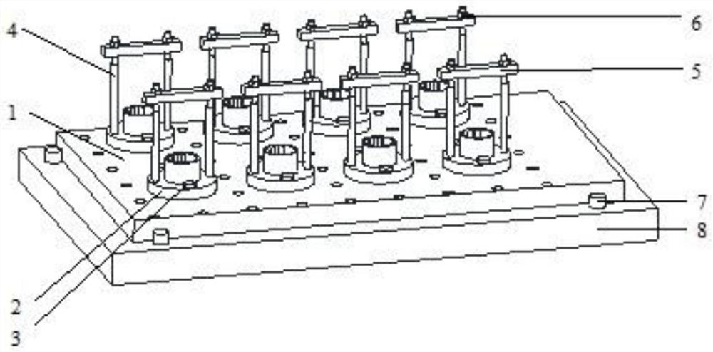
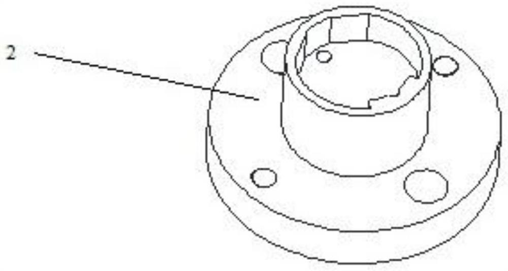
[0030] The invention provides a clamping device for flexible clamping to detect the workpiece of a rotary motor bracket assembly, improves the clamping method of the motor bracket assembly workpiece, realizes flexible locking, positioning and clamping; at the same time, it realizes fast workpiece clamping and batch detection. , to realize the detection of flexible clamping of the workpiece and improve the detection efficiency of the workpiece of the motor bracket assembly.

[0031] The flexible clamping device detects the clamping device of the workpiece of the rotary motor bracket assembly, such as figure 1 As shown, it specifically includes a detection substrate 1, a support block 7, a CMM flat plate 8 and n limit mechanisms; wherein, the CMM flat plate 8 is a horizontally placed plate-like structure; the detection substrate 1 is placed horizontally on the three-coordinate The ...


PUM


Abstract

The invention relates to a clamping device for flexibly clamping and detecting a rotary motor support assembly workpiece, and belongs to the field of aerospace navigation application. Comprising a detection substrate, a leaning block, a three-coordinate measuring machine flat plate and n limiting mechanisms, wherein the three-coordinate measuring machine flat plate is of a horizontally placed plate-shaped structure; the detection substrate is horizontally placed on the upper surface of the three-coordinate measuring machine flat plate; the leaning block is fixedly mounted on the upper surface of the three-coordinate measuring machine flat plate; the leaning block is in contact with the side wall of the detection substrate, so that the detection substrate is positioned and limited; the n limiting mechanisms are fixedly mounted on the upper surface of the detection substrate; the installation positions of the n limiting mechanisms are set according to needs, and each limiting mechanism achieves limiting and fixing of one external motor support assembly. The clamping mode of a motor support assembly workpiece is improved, and flexible locking, positioning and clamping are achieved; and meanwhile, rapid workpiece clamping and batch detection are achieved, flexible workpiece clamping detection is achieved, and meanwhile the motor support assembly workpiece detection efficiency is improved.

Description

technical field [0001] The invention belongs to the application field of aerospace navigation, and relates to a clamping device for flexible clamping and detecting workpieces of a rotary motor support assembly. Background technique [0002] The gyro accelerometer is used as a high-precision platform inertial instrument, and its working stability and accuracy directly affect the use accuracy of the platform system. The mechanical instrument has high precision, many factors affecting reliability, and the assembly process is complicated. After analysis, the stability and functionality of the center of mass of the float assembly are mainly determined by the stability of the installation structure of the dynamic pressure gyro motor inside the float, so it is the assembly of the float assembly. The key process of the whole instrument, the motor installation is the key process of the float assembly. [0003] In order to ensure the consistency of the motor installation process, it ...

Claims


Application Information

Patent Timeline
IPC IPC(8): B25B11/00G01B5/00G01B21/00
CPCB25B11/00G01B21/00G01B5/0002
Inventor 米军辉庞国旺张荣李思达刘元飞
Owner BEIJING INST OF AEROSPACE CONTROL DEVICES
Learn More