Total reflection type liquid crystal display panel

A liquid crystal display panel, total reflection technology, applied in instruments, nonlinear optics, optics, etc., can solve the problem of low reflectivity and achieve the effect of improving reflectivity

Pending Publication Date: 2022-08-02
SHENZHEN CHINA STAR OPTOELECTRONICS TECH CO LTD
View PDF8 Cites 0 Cited by
  • Summary
  • Abstract
  • Description
  • Claims
  • Application Information

AI Technical Summary

Problems solved by technology

[0005] To sum up, the existing reflective liquid crystal display panel has the problem of low reflectivity

Method used


Image

  • Total reflection type liquid crystal display panel
  • Total reflection type liquid crystal display panel
  • Total reflection type liquid crystal display panel

Examples


Embodiment Construction

[0034] The following descriptions of the various embodiments refer to the accompanying drawings to illustrate specific embodiments in which the present application may be practiced. Directional terms mentioned in this application, such as [upper], [lower], [front], [rear], [left], [right], [inner], [outer], [side], etc., are only for reference Additional schema orientation. Therefore, the directional terms used are used to describe and understand the present application, rather than to limit the present application. In the figures, structurally similar elements are denoted by the same reference numerals.

[0035] The present application will be further described below with reference to the accompanying drawings and specific embodiments.

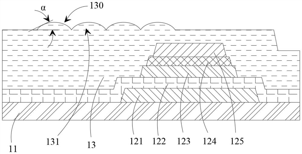
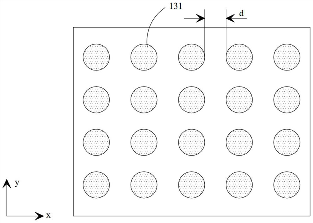
[0036] like figure 1 shown, figure 1 A schematic structural diagram of a total reflection type liquid crystal display panel provided in an embodiment of the present application, the liquid crystal display panel includes an array substrate...


PUM


Abstract

According to the total reflection type liquid crystal display panel, at least part of the uneven surface is arranged on the side, away from the substrate, of the flat layer of the total reflection type liquid crystal display panel, so that the reflection electrode can be arranged in the uneven shape along the uneven surface of the flat layer, and the reflection direction of light in the panel is changed; the light which cannot be reflected at the total reflection critical angle originally is reflected out of the panel, so that the reflectivity of the total reflection type liquid crystal display panel is improved.

Description

technical field [0001] The present application relates to the field of display technology, and in particular, to a total reflection type liquid crystal display panel. Background technique [0002] For a long time, the transmissive liquid crystal display technology has occupied the dominant position of the liquid crystal display panel (liquid crystal display, LCD). With the increasing market demand for low-power outdoor displays, the market prospect of reflective liquid crystal displays has gradually emerged. [0003] Compared with transmissive liquid crystal display panels, reflective liquid crystal display panels can display clearly under ambient light sources, do not require a backlight, have the advantages of thin body and low power consumption, and have good market application prospects in the field of outdoor display. [0004] However, the current reflective LCD TV panel faces a common problem, that is, the reflectivity is small. At present, the reflectivity of the lar...

Claims


Application Information

Patent Timeline
Patent Type & Authority Applications(China)
IPC IPC(8): G02F1/1335G02F1/1362
CPCG02F1/133553G02F1/1362G02F1/1335G02F1/1343G02F1/133555G02F1/133504G02F1/13439G02F1/133514G02F1/133357G02F2201/48G02F2203/02
Inventor 柳吴广赵迎春刘一诺卢颖高健博
Owner SHENZHEN CHINA STAR OPTOELECTRONICS TECH CO LTD
Why Eureka
Try Eureka