
Spaceborne SAR (synthetic aperture radar) system transceiving delay stabilization method and device and electronic equipment

A technology of sending and receiving time delay and stabilization method, which is applied in the direction of radio wave measurement systems and instruments, can solve problems such as sending and receiving time delay errors, and achieve the effects of ensuring stability, wide adaptability, and strong versatility

Active Publication Date: 2022-08-02
AEROSPACE INFORMATION RES INST CAS
View PDF5 Cites 0 Cited by
  • Summary
  • Abstract
  • Description
  • Claims
  • Application Information

AI Technical Summary

Problems solved by technology

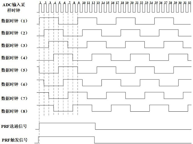
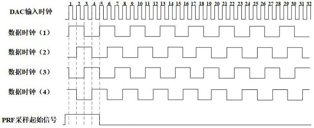
according to image 3 The shown FPGA data clock will have a timing relationship between data clock (1) and data clock (4) before reset, that is, there are four possibilities for the relationship between the sampling clock and the FPGA data clock before the ADC is reset, and the impact on the transmission and reception delay of the system is each time The initial delay of the system due to clock jitter will have a system delay error of 0, 1, 2, 3 times the sampling clock cycle (1 sampling clock cycle 1.38ns)
After the ADC is reset, the relationship between the sampling clock and the FPGA data clock is fixed, which is one of the four relationships. Taking the data clock (2) as an example, due to the instability of the sampling clock, if the falling edge of the PRF sampling start signal 1 and the data clock (2) Rising edge alignment, SAR system echo sampling time will jump at the 5th sampling or 13th sampling clock of ADC, which will bring 8 sampling clock cycles (11.1ns) system sending and receiving delay error, like Figure 4 shown

Method used


Image

  • Spaceborne SAR (synthetic aperture radar) system transceiving delay stabilization method and device and electronic equipment
  • Spaceborne SAR (synthetic aperture radar) system transceiving delay stabilization method and device and electronic equipment
  • Spaceborne SAR (synthetic aperture radar) system transceiving delay stabilization method and device and electronic equipment

Examples


Embodiment Construction

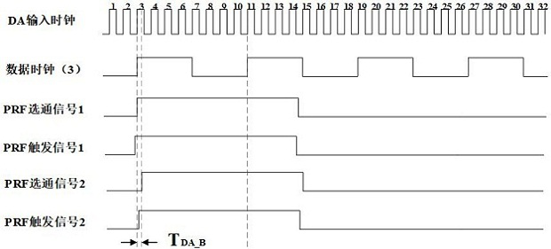
[0043] In the prior art, in the measurement of the transmission and reception delay of the SAR system, the uncertain error caused by the jump in the transmission time and the echo sampling start time cannot meet the stability requirements of the transmission and reception delay of the system. In view of this, the present invention provides A method, device and electronic device for stabilizing the sending and receiving delay of a spaceborne SAR system. The system echoes are recorded multiple times by delaying a PRF trigger signal before and after a high-speed DAC reset, and delaying a PRF sampling start signal before and after a high-speed ADC reset. After pulse compression processing, we can find out whether the delay of the system has jumped, so as to find a system that can ensure that every time the system is turned on, the transmission time and the echo sampling start time will not jump, and the system sending and receiving delay will remain Consistent delay combination val...


PUM


Abstract

The invention relates to a satellite-borne SAR (Synthetic Aperture Radar) system receiving and transmitting time delay stabilizing method and device and electronic equipment. By respectively delaying a PRF trigger signal before and after resetting of the high-speed DAC and respectively delaying a PRF sampling initial signal before and after resetting of the high-speed ADC, echo signals of the system are recorded for multiple times, and whether the time delay of the system jumps or not is obtained after pulse compression processing, so that a time delay signal which can ensure that the time delay of the system jumps every time when the system is started up is found. The transmitting time and the echo sampling starting time do not jump, and the transmitting and receiving time delays of the system are kept in a consistent time delay combination effective interval. According to the method, uncertain errors caused by jumping of the transmitting time and the echo sampling starting time in SAR system transmitting and receiving time delay measurement can be reduced, and the requirement for stability of system transmitting and receiving time delay is met.

Description

technical field [0001] The invention belongs to the technical field of synthetic aperture radar systems, and in particular relates to a method, device and electronic equipment for stabilizing the transmission and reception delay of a spaceborne SAR system. Background technique [0002] Synthetic Aperture Radar (SAR) is an active microwave imaging radar that can be installed on aircraft, satellites, missiles and other flight platforms. SAR has unique advantages in the application of disaster monitoring, resource exploration, ocean monitoring, environmental monitoring, surveying and mapping. Spaceborne multi-base interferometric synthetic aperture radar (Interferometric Synthetic Aperture Radar, InSAR) system is a new type of radar system that has emerged in recent years. It closely combines satellite formation technology and spaceborne SAR technology. Work collaboratively to complete tasks such as high-resolution imaging of large swaths, ground elevation measurement, ocean c...

Claims


Application Information

Patent Timeline
Patent Type & Authority Applications(China)
IPC IPC(8): G01S7/28G01S7/40
CPCG01S7/28G01S7/4004
Inventor 陈亚锋吴侠义冯晓晓岳海霞吕游毕见重刘晃剑刘开雨
Owner AEROSPACE INFORMATION RES INST CAS
Learn More