Front PTO transmission system, transmission case and tractor
A technology of transmission system and transmission box, which is applied in the field of transmission system and can solve the problems of small body, complex structure and increased machine mass
- Summary
- Abstract
- Description
- Claims
- Application Information
AI Technical Summary
Problems solved by technology
Method used
Image

Examples
Embodiment 1
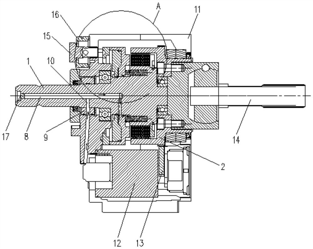
[0033] like figure 1 and figure 2 As shown, the present invention provides a front PTO transmission system, including a power output shaft 1 and an input gear 2, the power output shaft 1 can rotate around its own axis; the input gear 2 is coaxially rotated and sleeved on the power output shaft 1 It is combined with the power output shaft 1 through a hydraulic clutch and rotates with the power output shaft 1 or is separated from the power output shaft 1.
[0034] During transmission, the power is input by the input gear 2, and then the input gear 2 is combined with the power output shaft 1 through the hydraulic clutch and rotates with the power output shaft 1 to realize the rapid output of power; or separate from the power output shaft and stop the transmission, the structure is simple , the design is reasonable.
[0035] This embodiment can realize fast output of power, high transmission efficiency, compact structure, high integration, small occupied space and light weight....
Embodiment 2
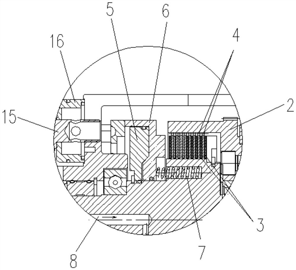
[0038] On the basis of Embodiment 1, in this embodiment, the hydraulic clutch includes a hydraulic drive mechanism and a friction plate assembly, one end of the input gear 2 extends to the other end of the power output shaft 1, and a mounting cavity is formed between the input gear 2 and the power output shaft 1 , that is, the input gear 2 has a cylindrical structure with one end closed and one end open, and a circular hole is arranged at the center of the closed end, and the circular hole is rotatably connected with the power output shaft 1 through a bearing; the friction plate assembly is installed on the power output shaft 1 Corresponding to the parts in the installation cavity, and are respectively connected with one end of the power output shaft 1 and one end of the input gear 2; the hydraulic drive mechanism is used to drive the friction plate assembly to combine or separate the power output shaft 1 and the input gear 2.
[0039] During transmission, the friction plate as...
Embodiment 3
[0042] On the basis of Embodiment 2, in this embodiment, the friction plate assembly includes a plurality of friction plates 3 and a plurality of steel plates 4 , and the plurality of friction plates 3 and the plurality of steel plates 4 are alternately coaxial along the axial direction of the power output shaft 1 . It is sleeved on one end of the power output shaft 1, and can slide along the axial direction of the power output shaft 1 respectively; the inner sides of the plurality of friction plates 3 are respectively provided with internal teeth meshing with the external teeth on one end of the power output shaft 1. The outer teeth of each steel plate 4 are respectively provided with external teeth meshing with the internal teeth on the inner side of one end of the input gear 2 .
[0043] During transmission, a plurality of friction plates 3 are respectively meshed with the power output shaft 1, and a plurality of steel plates 4 are respectively meshed with the input gear 2. ...
PUM
 Abstract
Description
Claims
Application Information
 - R&D
- Intellectual Property
- Life Sciences
- Materials
- Tech Scout
- Unparalleled Data Quality
- Higher Quality Content
- 60% Fewer Hallucinations
Browse by: Latest US Patents, China's latest patents, Technical Efficacy Thesaurus, Application Domain, Technology Topic, Popular Technical Reports.
© 2025 PatSnap. All rights reserved.Legal|Privacy policy|Modern Slavery Act Transparency Statement|Sitemap|About US| Contact US: help@patsnap.com