
Vehicle gas circuit control device and control method

A technology of air circuit control and control method, which is applied in the direction of pump device, pump control, vehicle parts, etc., can solve the problems of complicated installation, mixing, and reducing the service life of auto parts, so as to improve vehicle performance, facilitate installation, and reduce fuel consumption. Effect

Pending Publication Date: 2022-08-02
SINO TRUK JINAN POWER
View PDF1 Cites 0 Cited by
  • Summary
  • Abstract
  • Description
  • Claims
  • Application Information

AI Technical Summary

Problems solved by technology

[0002] The ordinary mechanical air circuit device of traditional vehicles can only start to unload when the system air pressure is greater than the upper limit, and start to inflate when the system air pressure is lower than the system lower limit; when the bodywork is working, the chassis control air source connected to the service brake air source pipeline is Yes, water and other impurities may be mixed in the air circuit, and it can also be operated in the chassis cab, but these operations will affect the work of the bodywork, and even cause safety accidents; although electronically controlled air circuit devices have emerged recently, the structure is complicated, The installation is complicated, and the control is not fully combined with the working conditions of the car
[0003] Invention name Control device for pneumatic vehicles, patent number CN103231707B, discloses a control device for pneumatic vehicles. The control device consists of a data unit, an air injection module, a compressor module, and a heating module. The operation controls the opening and duration of the flow valve, thereby adjusting the power output of the aerodynamic engine, but the intelligence and integration are low, and the gas has not been dried and filtered, which reduces the service life of the auto parts to a certain extent and increases the maintenance cost

Method used


Image

  • Vehicle gas circuit control device and control method
  • Vehicle gas circuit control device and control method
  • Vehicle gas circuit control device and control method

Examples


Embodiment Construction

[0023] The present invention will be further described below in conjunction with the accompanying drawings and embodiments: In order to clearly illustrate the technical characteristics of this solution, the present invention will be described in detail below through specific embodiments and in conjunction with the accompanying drawings. The following disclosure provides many different embodiments or examples for implementing different structures of the invention. In order to simplify the disclosure of the present invention, the components and arrangements of specific examples are described below. Furthermore, the present invention may repeat reference numerals and / or letters in different instances. This repetition is for the purpose of simplicity and clarity and does not in itself indicate a relationship between the various embodiments and / or arrangements discussed. It should be noted that the components illustrated in the figures are not necessarily drawn to scale. Descript...


PUM


Abstract

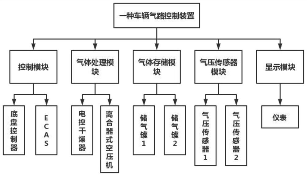
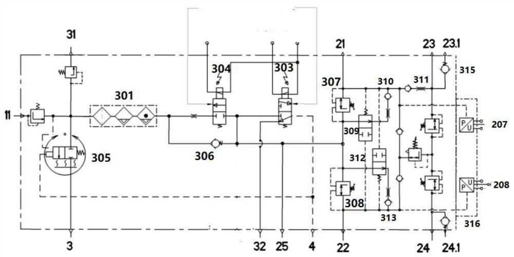
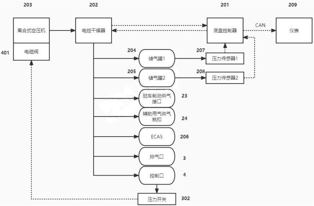
The invention discloses a vehicle gas path control device and method. The control device comprises a control module, a gas processing module, a gas storage module, a gas pressure sensor module, a display module and a plurality of air pipelines. When the system pressure is larger than a certain value, the unloading valve is opened, the pressure of the pressure switch loop is increased, the pressure switch is opened, the air compressor electromagnetic valve is driven, and the air compressor is disengaged to stop inflating; on the contrary, when the system pressure is smaller than a certain value, the chassis controller controls the air compressor to be engaged to start inflating; when regeneration is needed, the unloading valve and the regeneration valve are opened, and water impurities in the pipeline and the dryer are filtered; the controller sets different threshold values for regeneration, inflation and inflation stopping according to the working condition of the vehicle, under the condition that the requirement for safe gas use of the vehicle is met, the reverse towing working condition is reasonably utilized for more inflation, energy recovery is achieved, and oil consumption is reduced; and in addition, the auxiliary starting function can be achieved, and the starting performance of the whole vehicle is improved.

Description

technical field [0001] The invention relates to the technical field of vehicle electronic control, in particular to a vehicle air circuit control device and a control method. Background technique [0002] The ordinary mechanical air circuit device of traditional vehicles can only start unloading when the system air pressure is greater than the upper limit, and start pumping when the system air pressure is less than the lower limit of the system; when the bodywork is working, the chassis control air source connected to the service brake air source pipeline is filled with air. Yes, impurities such as water may be mixed in the gas circuit, and operations can also be performed in the chassis cab, but these operations will affect the work of the bodywork and even cause safety accidents; although electronically controlled gas circuit devices have recently emerged, but the structure is complex, The installation is complicated, and the control is not fully integrated with the workin...

Claims


Application Information

Patent Timeline
Patent Type & Authority Applications(China)
IPC IPC(8): B60R16/08B60T17/00F04B41/02F04B39/16F04B49/03F04B49/02F17D1/07F17D3/01
CPCB60R16/08B60T17/004F04B41/02F04B39/16F04B49/03F04B49/022F17D1/07F17D3/01
Inventor 周在芳路志强孙志春谢孔昶
Owner SINO TRUK JINAN POWER
Learn More