Automatic conveying type paint spraying device for furniture processing

A technology for automatic conveying and furniture, applied in the direction of injection device, liquid injection device, etc.

Active Publication Date: 2022-08-02
ANHUI YOUSHUN WOOD IND
View PDF8 Cites 1 Cited by
  • Summary
  • Abstract
  • Description
  • Claims
  • Application Information

AI Technical Summary

Problems solved by technology

[0002] The painting work of fixture processing is to spray paint the entire board, and then carry out subsequent cutting and assembly of the painted board. In the prior art, when the primer is sprayed, it does not require high-precision processing. The assembly line equipment will be used for automatic painting processing, which greatly improves the efficiency of the painting work of the board. During the painting process, in order to ensure the full coverage of the board, the surface of the conveyor belt for transportation must adhere to the paint during painting. There is also an adaptation problem between the plate size and the conveyor belt during transportation. To solve the above problems, it is necessary to improve the adaptability of the conveyor belt structure

Method used


Image

  • Automatic conveying type paint spraying device for furniture processing
  • Automatic conveying type paint spraying device for furniture processing
  • Automatic conveying type paint spraying device for furniture processing

Examples


Embodiment 1

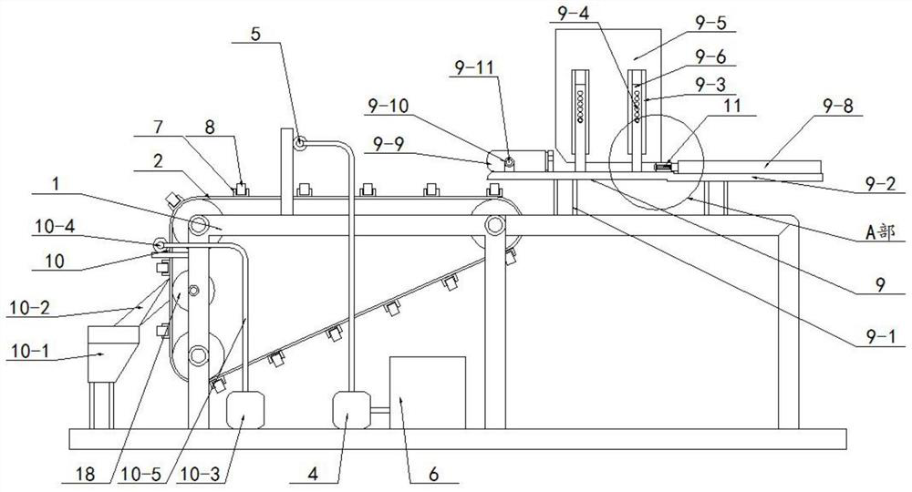
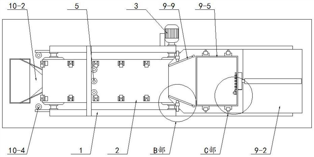
[0048] like figure 1 , 2As shown, this embodiment includes a frame 1, a conveyor belt 2, a drive motor 3, a water pump 4, a nozzle 5, and a storage tank 6, wherein the conveyor belt 2 is screwed on the frame 1 through bearings, and the drive motor 3 is fixed to the machine through screws. On the frame 1, and the drive motor 3 and the rear end of the right shaft of the conveyor belt 2 are driven and arranged, the nozzle 5, the water pump 4, and the storage tank 6 are all fixed on the frame 1 by screws, and the nozzle 5 is arranged above the conveyor belt 2, The nozzle 5 is connected with the discharge end of the water pump 4 through a pipeline, and the feed end of the water pump 4 and the discharge end of the storage tank 6 are connected through a pipeline. It also includes:

[0049] Slots 7, described slots 7 are several, and the front and rear equal numbers are divided into two groups to set, and the front and rear two groups of slots 7 are symmetrically fixed on the front a...

Embodiment 2

[0055] like figure 1 , 2 As shown, on the basis of the above-mentioned Embodiment 1, the loading positioning member 9 includes:

[0056] A support frame 9-1, the support frame 9-1 is fixed on the frame 1 by screws, and the support frame 9-1 is arranged on the right side of the conveyor belt 2;

[0057] The bottom plate 9-2, the bottom plate 9-2 is fixed on the support frame 9-1 by screws, and the bottom plate 9-2 is arranged above the conveyor belt 2;

[0058] There are several guide rails 9-3, and the front and rear are symmetrically fixed on the upper surface of the base plate 9-2 by screws. The guide rails 9-3 are equally spaced from top to bottom. 9-4 positioning holes;

[0059] The feeding box 9-5, the feeding box 9-5 is arranged between the guide rails 9-3 on the front and rear sides;

[0060] Guide groove 9-6, the guide groove 9-6 is fixed on the outer side wall of the feeding box 9-5 by screws, and the guide rail 9-3 is movably inserted in the guide groove 9-6;

...

Embodiment 3

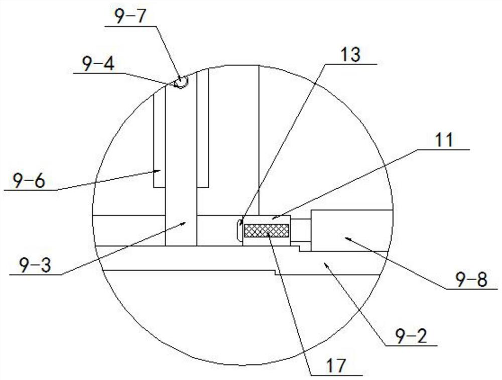
[0068] like figure 1 , 2 , 3 and 5, on the basis of the above-mentioned Embodiment 2, the output end of the feeding electric push rod 9-8 is fixed with a pushing plate 11 by screws, and the pushing plate 11 is arranged on the feeding box 9 Below -5, and the ejector plate 11 is movably abutted on the upper surface of the bottom plate 9-2, an installation cavity 12 is opened on the left side wall of the ejector plate 11, and a support wheel 13 is arranged in the installation cavity 12, and is arranged with the support wheel 13. The ejector plates 11 are rotated through the rotating shaft, and the left end of the support wheel 13 extends to the left side of the installation cavity 12;

[0069] With the above design scheme, the feeding electric push rod 9-8 pushes the pusher plate 11 against the right side of the raw material plate, and then the support wheel 13 pushes the plate against the plate, and then pushes the plate to the left, and the plate passes through the guide plate...


PUM


Abstract

The invention discloses an automatic conveying type paint spraying device for furniture processing, and relates to the technical field of plate paint spraying equipment, a plurality of insertion grooves are arranged and are divided into two groups in a front-back equal-number mode, the front and back groups of insertion grooves are symmetrically and fixedly formed in the front and back sides of the surface of a conveying belt, limiting blocks are movably inserted into the insertion grooves, and a feeding positioning piece is arranged on a rack; the paint recycling part is arranged on the rack and is arranged on the left side of the conveying belt; according to the paint spraying device, the feeding structure and the waste recycling structure are arranged, the feeding structure is provided with an adaptive position guiding structure so as to adapt to workpieces of different sizes, the recycling structure can achieve gathering and recycling of waste and can adapt to different waste distribution conditions, and then the paint spraying device integrating feeding and recycling is formed.

Description

technical field [0001] The invention relates to the technical field of sheet painting equipment, in particular to an automatic conveying type painting device for furniture processing. Background technique [0002] The spray painting work of fixture processing is to spray paint the whole plate, and then carry out subsequent cutting and assembly of the painted plate. Assembly line equipment will be used for automatic painting processing, which greatly improves the painting efficiency of the board. During painting, in order to ensure full coverage of the board, the surface of the conveyor belt for conveying must adhere to the paint during painting, and it is There is also a problem of adaptation between the size of the plate and the conveyor belt during conveying. In response to the above problem, it is necessary to improve the adaptability of the conveyor belt structure. SUMMARY OF THE INVENTION [0003] The purpose of the present invention is to aim at the defects and defi...

Claims


Application Information

Patent Timeline
Patent Type & Authority Applications(China)
IPC IPC(8): B05B13/02B05B9/04B05B14/20
CPCB05B13/0221B05B9/0409B05B14/20Y02P70/10
Inventor 殷久和殷久珍冯丽华杨远林
Owner ANHUI YOUSHUN WOOD IND
Why Eureka
Try Eureka