


Quick Research
Generate reliable direction feasibility study reports for your R&D in just a few steps.

Technical Q&A
Discover and master advanced knowledge NOW. Basics, ideas, possibilities, all at once.

Find Solutions
As an expert in R&D theories, this can generate solutions to your technical problems instantly.

Evaluate Feasibility
Analyze your overall solution with one click, know your potential R&D risks in advance.

Monitor Landscape
Get weekly tech updates, stay abreast of the latest tech innovations and key insights.
Battery module
A technology of battery modules and batteries, which is applied to battery components, secondary batteries, circuits, etc., can solve the problems of slow heat dissipation, high assembly efficiency, and low assembly efficiency of battery modules, so as to improve convenience and Assembling speed, stable position, and the effect of extending the service life
- Summary
- Abstract
- Description
- Claims
- Application Information
AI Technical Summary
Problems solved by technology
Method used
Image


Examples
Embodiment 1
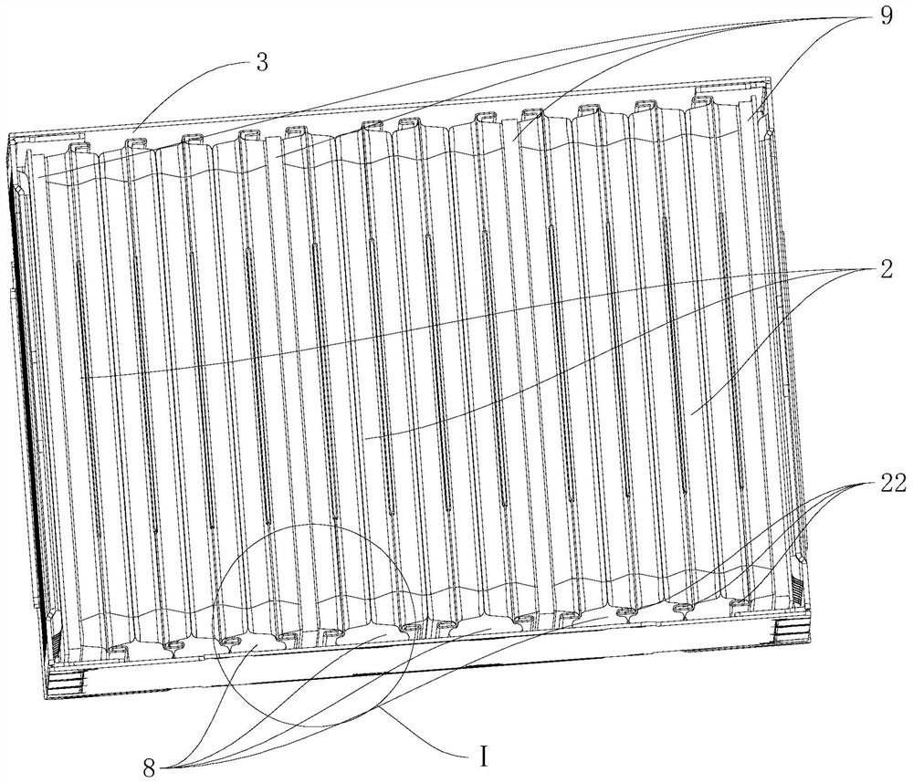
[0139] A battery module 100, such as figure 1 As shown, it includes: a plurality of bus bars 1 , a plurality of groups of cells 2 , a housing 3 , two end brackets 4 and two bus bar protection shells 7 .
[0140] Among them, such as figure 1 As shown, each group of cells 2 has tabs 21 extending toward both ends.
[0141] like figure 1 As shown, the housing 3 is provided with a accommodating cavity 31 for accommodating multiple groups of cells 2, and the bottom of the housing 3 is provided with a plurality of thermally conductive supports 8 toward the cells 2 (for the specific structure of the thermally conductive support 8, please refer to image 3 ), the bottom of the thermally conductive support 8 is connected to the bottom wall of the housing 3 , and the top of the thermally conductive support 8 abuts against the cell 2 .
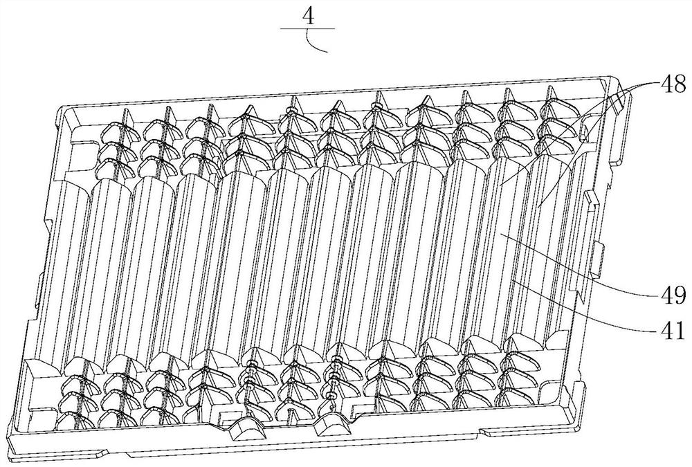
[0142] The two end brackets 4 are connected on both sides of the accommodating cavity 31 , the end brackets 4 are arranged at intervals from the heat ...
Embodiment 2
[0147] A battery module 100, on the basis of Embodiment 1, such as image 3 and Figure 4 As shown, the bottom of each group of cells 2 is provided with a bent cell support portion 22, the adjacent two groups of cell support portions 22 are spaced apart, and some adjacent cell support portions 22 are connected with a thermal conductor. The supporting member 8, the upper part of the thermally conductive supporting member 8 abuts the two groups of cells 2 respectively.
[0148] like Figure 4 As shown, the thermally conductive support 8 includes a first support body 81, a second support body 82 and a third support body 83, the first support body 81 and the second support body 82 are connected in a stepped shape, and the second support body 82 and the first support body 82 The cell support parts 22 are connected between the support bodies 81 , the bottom of the first support body 81 is connected to the bottom wall; the third support body 83 is connected to the upper part of the...
Embodiment 3
[0150] A battery module 100, on the basis of Embodiment 1, such as Figure 7 As shown, the side of the end bracket 4 facing the bus bar 1 is protruded with a plurality of clamping ribs 43 and a plurality of positioning columns 44, the clamping ribs 43 are in contact with the edge of the bus bar 1, and the positioning columns 44 are in contact with the bus bar 1. Row 1 positioning fit.
[0151] The end bracket 4 is respectively provided with four first clamping feet 42 , one of the four first clamping feet 42 extends outward from the clamping rib 43 , and two of the four first clamping feet 42 . The orientations of the first clips 42 are different, such as Figure 5 As shown, the busbar protection shell 7 is provided with four clamping holes 71 corresponding to the first clamping feet 42 .
[0152] like Figure 5 As shown, the first positioning assembly 5 includes a positioning insert 51 provided on the end bracket 4 and a first socket 52 provided on the busbar protection sh...
PUM
 Abstract
Description
Claims
Application Information
 - R&D Engineer
- R&D Manager
- IP Professional
- Industry Leading Data Capabilities
- Powerful AI technology
- Patent DNA Extraction
Browse by: Latest US Patents, China's latest patents, Technical Efficacy Thesaurus, Application Domain, Technology Topic, Popular Technical Reports.
© 2024 PatSnap. All rights reserved.Legal|Privacy policy|Modern Slavery Act Transparency Statement|Sitemap|About US| Contact US: help@patsnap.com