Power supply quick wake-up circuit and method
A wake-up circuit and power supply technology, applied in program control, instrument, computer control, etc., can solve the problems of slow system establishment and long circuit startup time, and achieve the effect of solving slow wake-up and simple circuit structure
- Summary
- Abstract
- Description
- Claims
- Application Information
AI Technical Summary
Problems solved by technology
Method used
Image
Examples
Embodiment 1
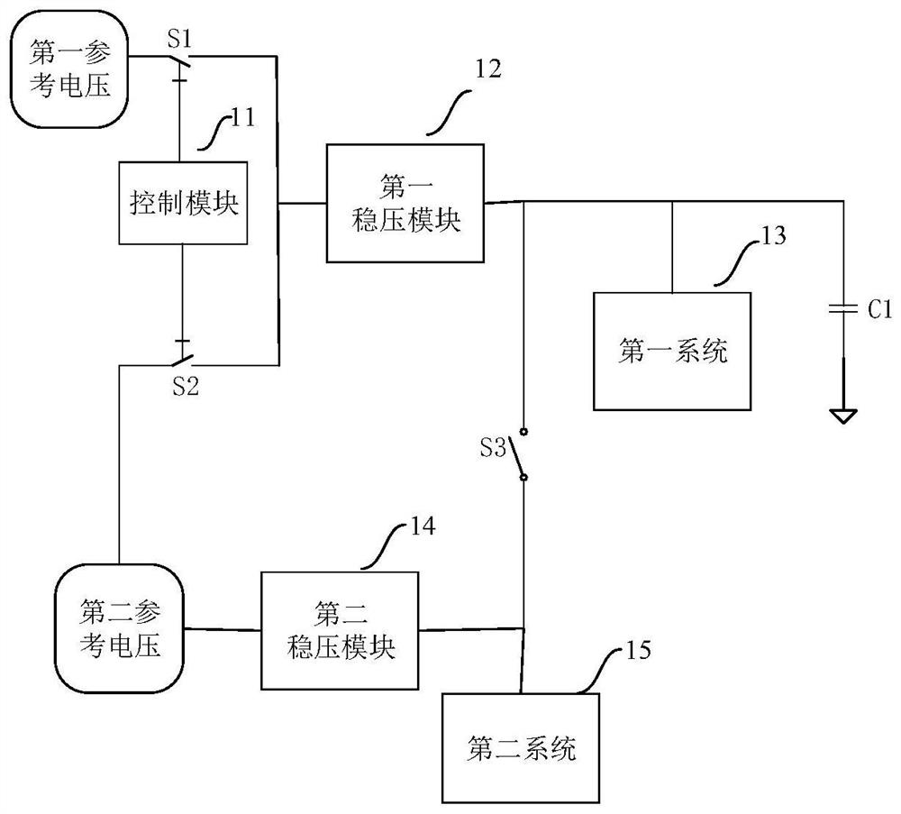
[0028] like figure 1 As shown, this embodiment provides a power fast wake-up circuit including: a first voltage stabilization module 12, a second voltage stabilization module 14, a first switch S1, a second switch S2, a third switch S3, a first capacitor C1, a first A system 13 and a second system 15 .
[0029] Specifically, the power fast wake-up circuit further includes a control module 11, the control module 11 generates the first control signal and the second control signal based on a clock signal and a working mode switching signal, the first switch S1 and The state of the second switch S2 is opposite.
[0030] It should be noted that the control module 11 is a switching circuit that controls the states of the first switch S1 and the second switch S2. The switching circuit can switch between the power-on mode or the working mode according to different application requirements. Among them, the first switch S1 and the second switch S2 and the first voltage regulator modul...
Embodiment 2
[0041] This embodiment provides a method for fast wake-up of power supply, which is implemented based on the fast wake-up circuit of power supply in the first embodiment. When switching from low-power mode to high-performance mode, the following steps are involved:
[0042] S1: Receive the low power consumption to high performance mode switching signal, turn on the third switch S3, turn on the first reference voltage and the working state of the first voltage regulator module 12, and the first voltage regulator module 12 outputs a third voltage based on the second reference voltage , the second voltage regulator module 14 outputs a second voltage based on the second reference voltage, and charges the first capacitor C1 with the second voltage and the third voltage;
[0043] S2: After the first capacitor C1 is fully charged, the first system 13 starts to start, the second switch S2 is turned off, the first switch S1 is turned on, and the input of the first voltage regulator mod...
PUM
 Abstract
Description
Claims
Application Information
 - R&D Engineer
- R&D Manager
- IP Professional
- Industry Leading Data Capabilities
- Powerful AI technology
- Patent DNA Extraction
Browse by: Latest US Patents, China's latest patents, Technical Efficacy Thesaurus, Application Domain, Technology Topic, Popular Technical Reports.
© 2024 PatSnap. All rights reserved.Legal|Privacy policy|Modern Slavery Act Transparency Statement|Sitemap|About US| Contact US: help@patsnap.com


