Hysteresis type yarn tension adjusting device

A yarn tension and adjusting device technology, which is applied in the textile field, can solve problems such as increased hairiness, yarn extrusion damage, and yarn strength decrease, and achieves high operation selectivity and matching, stable tension control, and reduced bad friction Effect

Pending Publication Date: 2022-07-29
SUZHOU IMAGIN MACHINERY
View PDF0 Cites 0 Cited by
  • Summary
  • Abstract
  • Description
  • Claims
  • Application Information

AI Technical Summary

Problems solved by technology

[0002] At present, most of the single yarn or concentrated yarn tension devices used in doubling machines and winders on the market are spring clip type. By squeezing the spring, a certain pressure is generated on the left and right clips. The yarn in between will change (increase or decrease) the friction force on the yarn according to the clamping force pressed against the spring, thereby adjusting the tightness of the yarn (that is, the tension of the yarn), due to the tension of the yarn The control stability is poor. When the channel between the clips is blocked by foreign matter, the tension of the yarn will become smaller, which will cause an error between the set tension and the actual tension, and affect the forming of the yarn roll; the yarn is easily damaged by extrusion. When the passing yarn is a material that is prone to friction and pilling, excessive yarn tension will cause yarn strength to decrease, yarn defects and hairiness to increase, affecting yarn quality

Method used


Image

  • Hysteresis type yarn tension adjusting device
  • Hysteresis type yarn tension adjusting device
  • Hysteresis type yarn tension adjusting device

Examples


Embodiment Construction

[0017] In order to make the technical solutions of the present invention clearer, the present invention will be further described below with reference to the specific embodiments of the accompanying drawings.

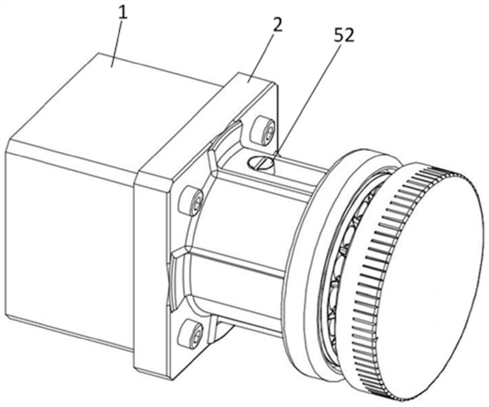
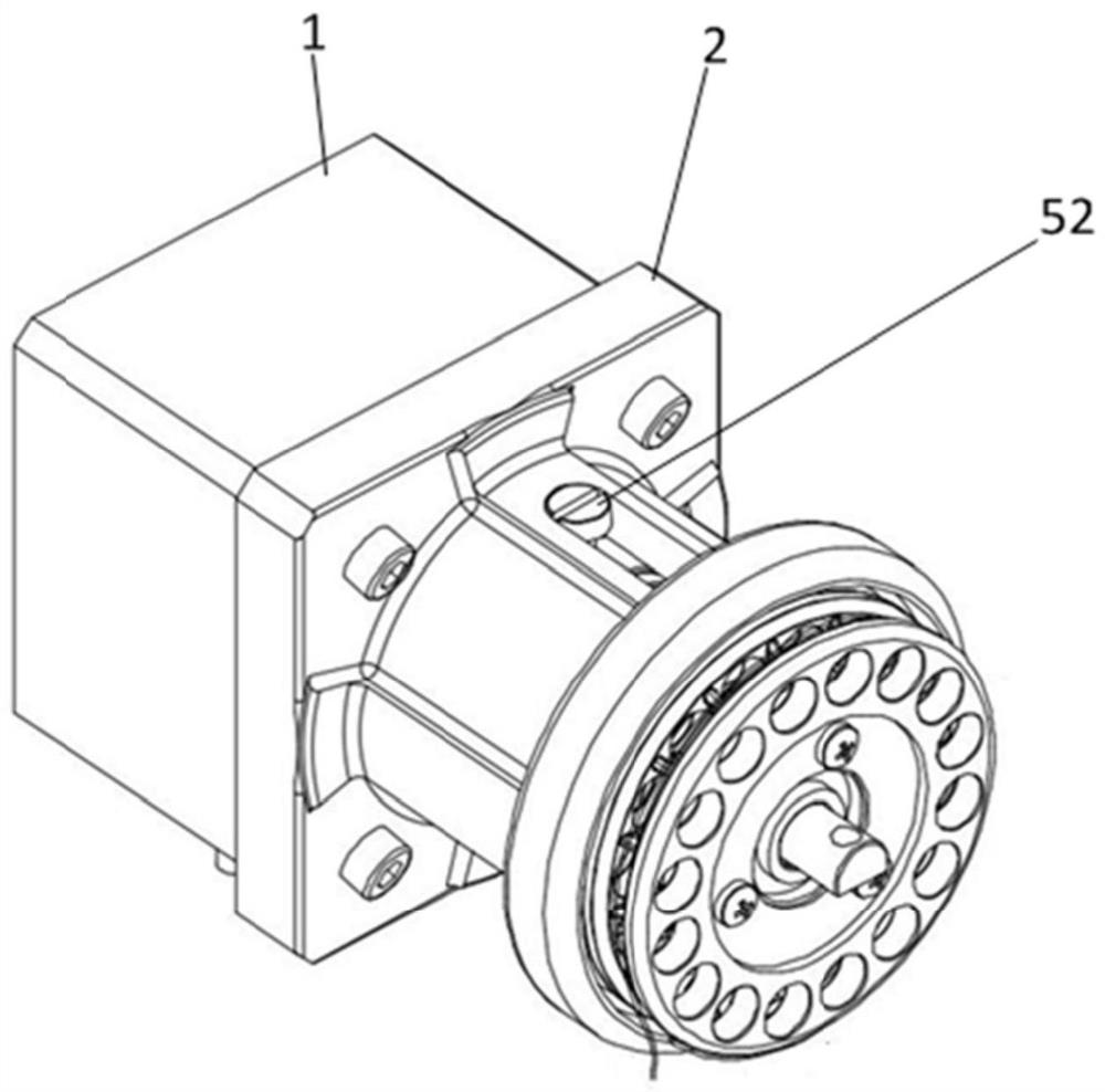
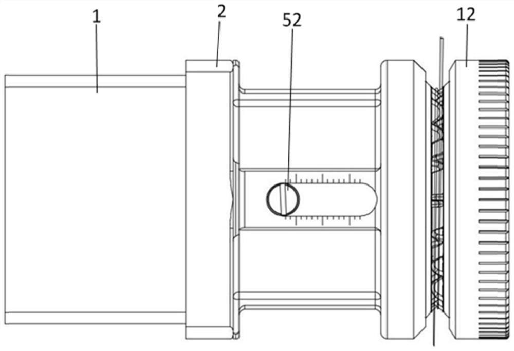
[0018] like Figure 1-6 As shown, a hysteresis yarn tension adjusting device according to an embodiment of the present invention includes a motor 1, and a cover 2 is provided on the outer surface of the motor 1 in the direction of the motor shaft 13, and is fixedly connected to each other by bolts 22, The outer surface of the casing 2 is provided with a long opening 21, and the rotating shaft 4 is a hollow structure as a whole. , the bottom of the motor shaft 13 is spliced ​​with a gasket 3, the side of the gasket 3 is located on the outer surface of the motor shaft 13 is spliced ​​with a rotating shaft 4, and is fixedly connected to each other through the positioning pin 41 and the positioning hole 44, so that the rotation The shaft 4 and the motor shaft 13 are fixedl...


PUM


Abstract

A hysteresis type yarn tension adjusting device comprises a motor, a housing is arranged on the outer side surface of the motor, a long-strip-shaped opening is formed in the outer side surface of the housing, a gasket is spliced to the bottom of a motor shaft, a rotating shaft is arranged on the side of the gasket, a first iron ring is in threaded connection with the rotating shaft through threads, and a magnetic ring penetrates through the rotating shaft to be attracted to the outer side surface of the first iron ring. The second iron ring, the first winch ring, the bearing and the second winch ring penetrate through the rotating shaft and are arranged on the side of the magnetic ring, the end cover is spliced and connected with the outer side surface of the second winch piece, and the locking screw penetrates through the spring and is connected with the fixing hole; original sliding friction is changed into rolling friction in a yarn winding mode, bad friction of the yarn is effectively reduced, and the problems of yarn faults, hairiness and neps of the yarn are solved.

Description

technical field [0001] The invention relates to the field of textile technology, in particular to a hysteresis type yarn tension adjusting device. Background technique [0002] At present, most of the single yarn or concentrated yarn tension devices used in the yarn doubling machine and winding machine on the market are of the spring clip type. By squeezing the spring, a certain pressure is generated on the left and right clips. The yarn between the yarns will change (increase or decrease) the friction force on the yarn according to the clamping force of the spring, so as to adjust the tightness of the yarn (that is, the tension of the yarn). The control stability is poor. When the passage between the clips is blocked by foreign objects, the tension of the yarn will become smaller, which will cause an error between the set tension and the actual tension, which will affect the forming of the yarn roll; the yarn is easily damaged by extrusion. When the passing yarn is a mater...

Claims


Application Information

Patent Timeline
Patent Type & Authority Applications(China)
IPC IPC(8): B65H59/04B65H75/08B65H75/18D01H13/10
CPCB65H59/04B65H75/08B65H75/18D01H13/10B65H2701/31
Inventor 赵波姚卫康
Owner SUZHOU IMAGIN MACHINERY
Why Eureka
Try Eureka