Turnover device and turnover method for sensor production
A flipping device and sensor technology, which is used in transportation and packaging, typewriters, printing, etc., can solve the problem of blocking the position of the inkjet code
- Summary
- Abstract
- Description
- Claims
- Application Information
AI Technical Summary
Problems solved by technology
Method used
Image
Examples
Embodiment 1
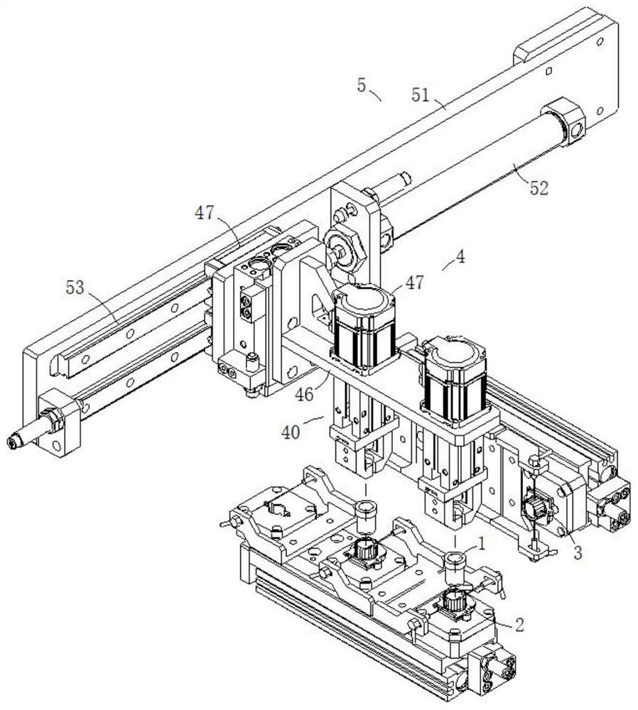
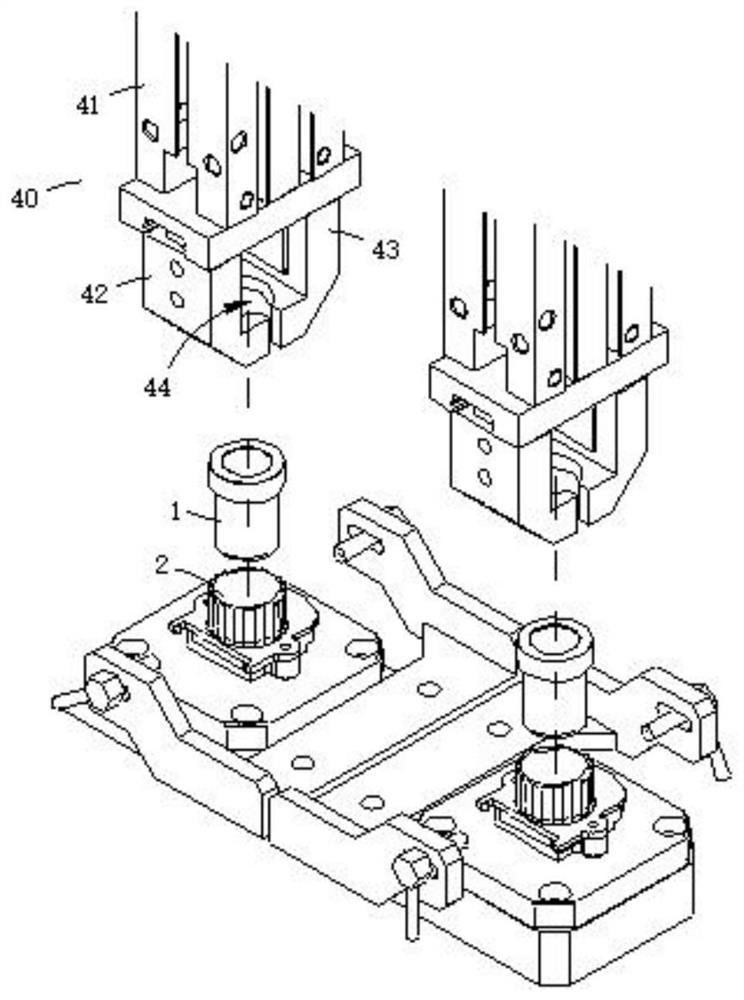
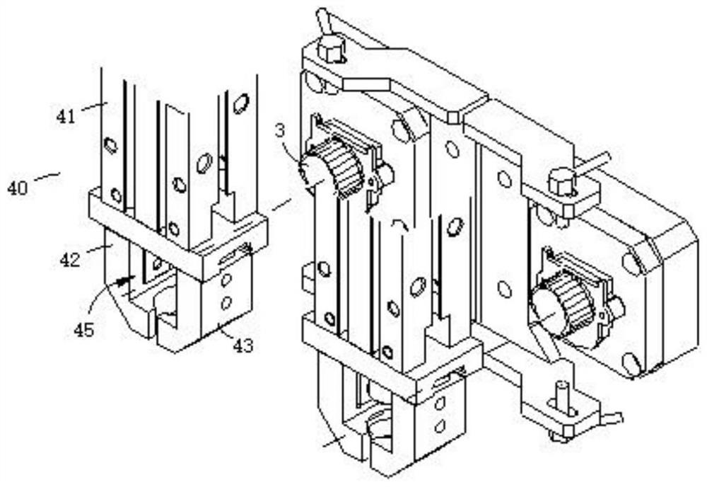
[0031] like Figure 1 to Figure 3 As shown in the figure, a flipping device for the production of sensor 1 according to the embodiment of the present invention includes an end face coding structure 2 for jetting coding on the end face of the sensor 1 , a side jetting coding structure 2 for jetting coding on the side face of the sensor 1 Structure 3, an inversion structure 4 for clamping and rotating the sensor 1, a driving structure 5 for moving the inversion structure 4 and the sensor 1, the driving structure 5 is drivingly connected to the inversion structure 4, and the inversion structure 4 includes a clamping end 40, in the The lower end of the clamping end 40 is formed with an end face coding hole 44, the lower end face of the sensor 1 extends out of the clamping end 40 from the end face coding hole 44, and the end face coding structure 2 is installed below the end face jetting hole 44, A side surface coding hole 45 is formed on the side of the clamping end 40 , the perip...
Embodiment 2
[0037] like Figure 1 to Figure 3 As shown in the embodiment of the present invention, in the flipping device used for the production of the sensor 1, in order to solve the problem of how to reciprocate the flipping structure 4, the driving structure 5 includes a driving bracket 51 and a driving cylinder 52, and one end of the driving cylinder 52 can pass through The driving bracket 51 can be fixedly connected by means of bolt connection, including but not limited to bolt connection, and the other end of the driving cylinder 52 can be fixedly connected to the clamping bracket 46 by means including but not limited to bolt connection, and the clamping bracket 46 can be slidably connected to the driving bracket 51 .
[0038] In order to solve the problem of how to guide the reciprocating movement of the inversion structure 4, the driving bracket 51 may be formed with a driving slideway 53 by means including but not limited to turning, and the clamping bracket 46 may be formed by m...
Embodiment 3
[0041] like Figure 1 to Figure 3 As shown, an inversion method for producing a sensor 1 according to an embodiment of the present invention includes the following steps.
[0042]Step 1: The flip structure 4 is acquired at the initial position and holds the sensor 1 in the first posture. It is easy to understand that the initial position inversion structure 4 is located at figure 1 The lower left end of the middle is the left end of the drive chute 53 . The first posture of the flip structure 4 is as follows figure 1 shown.
[0043] Step 2: The driving structure 5 moves the flip structure 4 to the coding position and keeps the flip structure 4 at the coding position. It is easy to understand that the coding position inversion structure 4 is located at figure 1 shown, that is, the right end of the drive chute 53 .
[0044] Step 3: At the same time as Step 2, the flip structure 4 is rotated from the first posture to the second posture and maintained in the second posture. ...
PUM
 Abstract
Description
Claims
Application Information
 - R&D
- Intellectual Property
- Life Sciences
- Materials
- Tech Scout
- Unparalleled Data Quality
- Higher Quality Content
- 60% Fewer Hallucinations
Browse by: Latest US Patents, China's latest patents, Technical Efficacy Thesaurus, Application Domain, Technology Topic, Popular Technical Reports.
© 2025 PatSnap. All rights reserved.Legal|Privacy policy|Modern Slavery Act Transparency Statement|Sitemap|About US| Contact US: help@patsnap.com


