
Cable protection and guide device

A guiding device and cable technology, which is applied in the direction of drag chains, hanging chains, etc., can solve the problems of troublesome disassembly operations, multiple workloads, and easy development, and achieve the effect of realizing disassembly and assembly operations and reducing the burden of disassembly and assembly operations

Active Publication Date: 2011-03-09
TSUBAKIMOTO CHAIN CO
View PDF7 Cites 0 Cited by
  • Summary
  • Abstract
  • Description
  • Claims
  • Application Information

AI Technical Summary

Problems solved by technology

[0004] However, in the above-mentioned conventional cable protection and guide device, when the cable protection and guide device is bent, both end edges in the longitudinal direction of the bending inner peripheral connecting plate are in excessive contact with the cables. Abrasion of cables is easy to develop, generation of abrasion powder and abrasion damage of cables may occur, so it is necessary to implement further measures to reduce abrasion of cables
[0005] In addition, in the conventional cable protection and guide device, since the partition wall member is installed in a state where the curved inner peripheral connecting plate and the curved outer peripheral connecting plate are grasped by the claws, the cable protection and guiding device is When disassembling and assembling, it is necessary to fit the claws of the partition wall member into the curved inner peripheral side connecting plate and the curved outer peripheral side connecting plate, and the disassembly operation becomes troublesome, and there is a problem that excessive work load is required

Method used


Image

  • Cable protection and guide device
  • Cable protection and guide device
  • Cable protection and guide device

Examples


Embodiment Construction

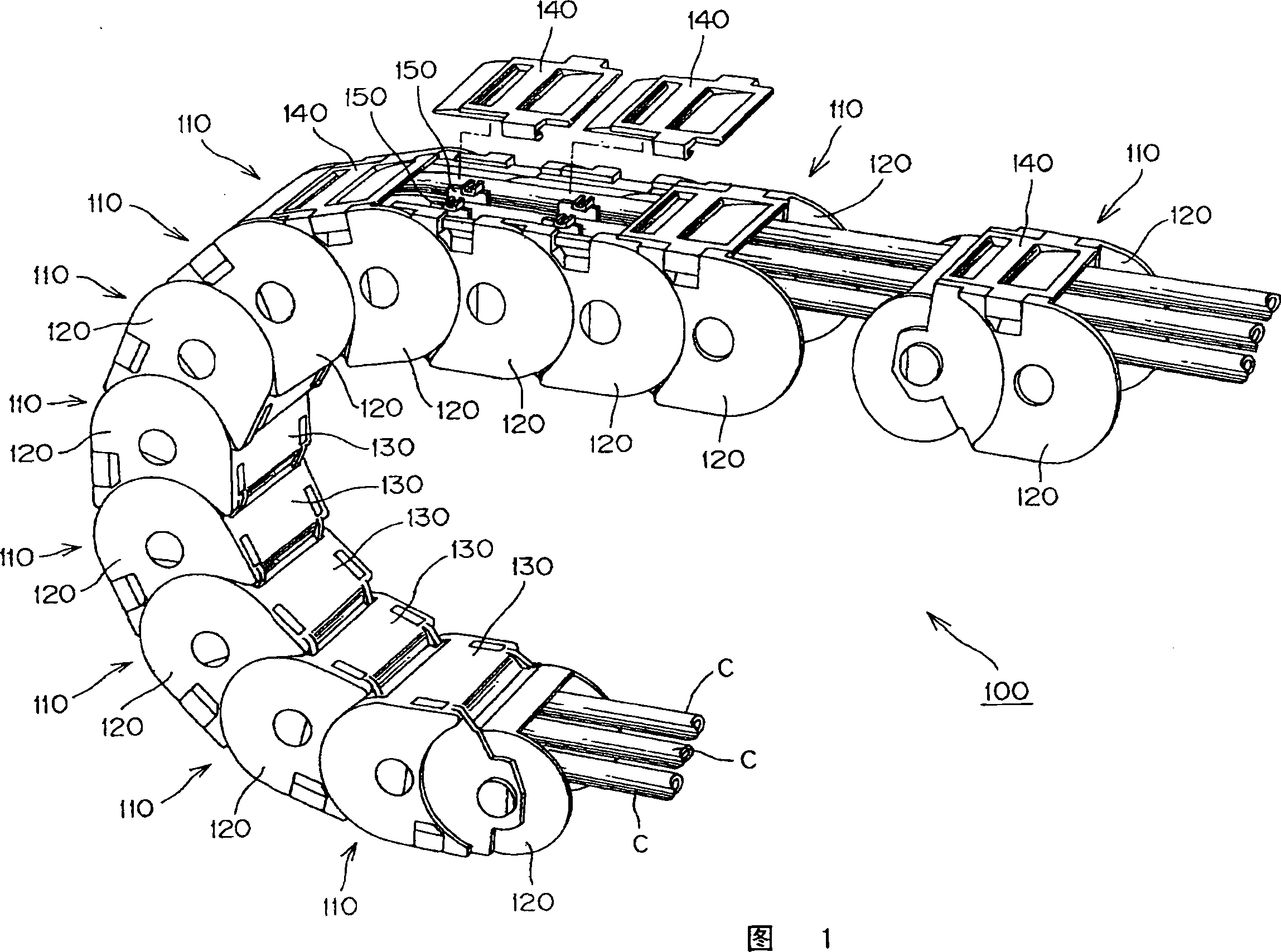
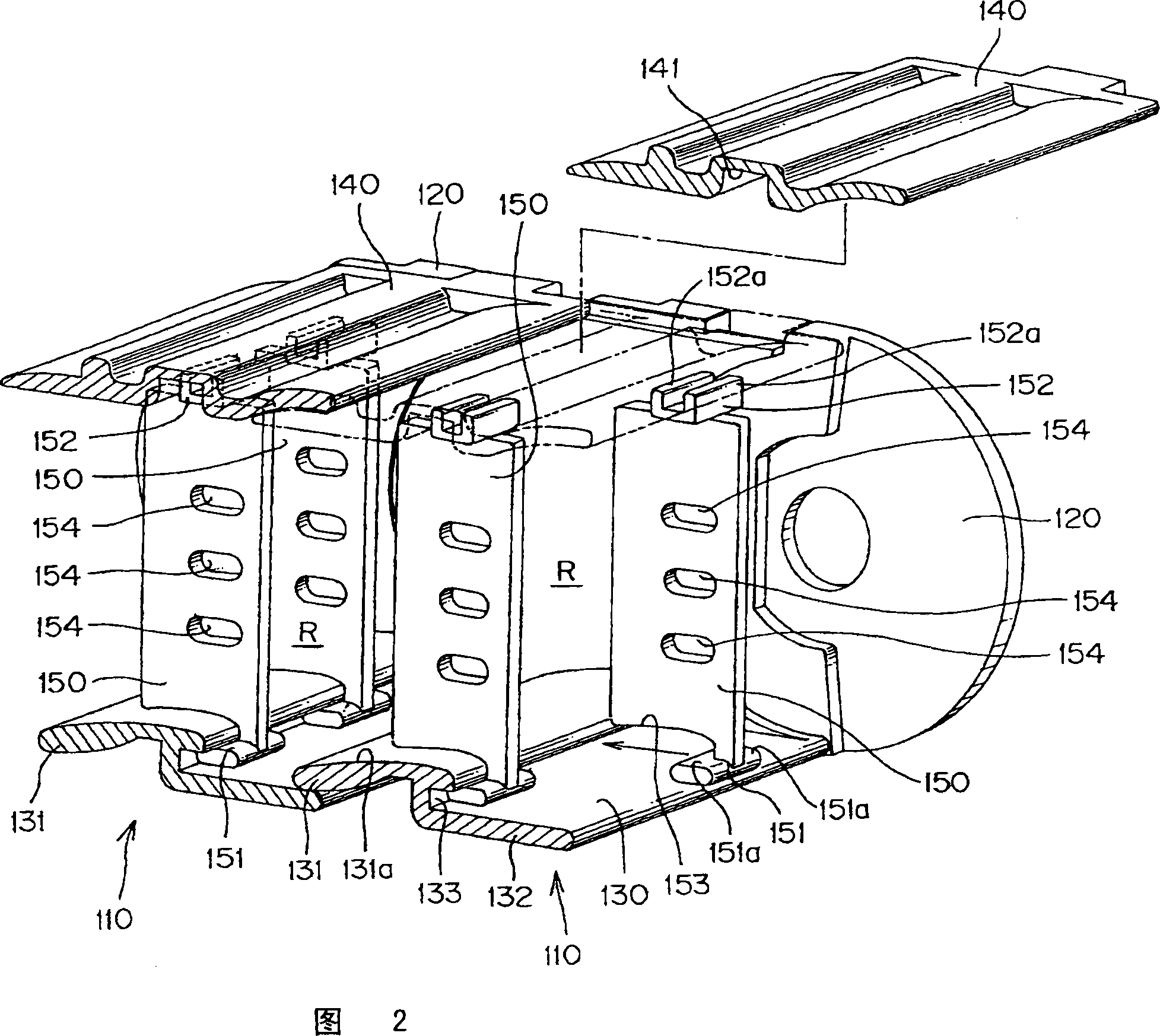
[0018] The present invention is the following cable protection and guide device, which connects a plurality of link frames of rectangular frame cross-section formed by bending the inner peripheral side connecting plate and bending the outer peripheral side connecting plate horizontally on a pair of left and right link plates respectively. , forming a cable storage space for accommodating, disposing, guiding and protecting cables, and between the curved inner peripheral connecting plate and the curved outer peripheral connecting plate, the wires in the above cable accommodating space are detachably provided. A partition wall plate for separating cables from left to right, wherein the curved inner peripheral connecting plate has abutting fins that abut on the cables, is integrally formed on the inner peripheral side of the bend than the abutting fins, and is bent when bent. The inner peripheral side fin which overlaps with the subsequent abutment fin, and the width direction of t...


PUM


Abstract

The invention provides a cable protection and guide device, which can restrain wear of cables relative to two end edges of lengthwise direction of flexional inner circumferential side plate, prevent the generation of wear powder and the damage of cables, and simplify the disassembly work of partitioning wall plate to lighten the load of decomposing assembling work. The cable protection and guide device (100) consists of a pair of left and right link plates (120, 120), a flexional inner circumferential side plate (130), a flexional outer circumferential side plate (140) and a partitioning wallplate (150). The flexional inner circumferential side plate includes an abutting flap (131), an inner circumferential side flap (132) and an inner locking groove (133) which is formed in a stepped manner over the width direction and locks the hook locking base end portion (151) of partitioning wall plate. The flexional outer circumferential side plate includes an outer locking groove (141) which extends in width direction of the cable accommodating space (R) and locks a locking front end portion (152) of the partitioning wall plate.

Description

technical field [0001] The present invention relates to a protection and guide device for cables, and more specifically, relates to accommodating cables such as cables or hoses for supplying electric power and energy of compressed gas to movable parts of industrial machinery, and is suitable for use in movable parts. A cable-type protective guide device that can safely and reliably guide protective cables even during moving. Background technique [0002] Conventionally, there is known a cable protection and guide device in which a link frame having a rectangular frame cross-section of a connecting plate is horizontally mounted on the curved inner peripheral side and the curved outer peripheral side of a pair of left and right link plates. A plurality of connecting pins and connecting pin holes on the link plate are flexibly connected to each other to form a cable storage space for inserting and guiding and protecting cables, and the cable storage space can be freely installe...

Claims


Application Information

Patent Timeline
Patent Type & Authority Patents(China)
IPC IPC(8): F16G13/16
CPCF16G13/16
Inventor 小宫庄一郎
Owner TSUBAKIMOTO CHAIN CO
Learn More