
Hydraulic engineering desilting device and desilting method

A dredging device and water conservancy engineering technology, applied in separation methods, chemical instruments and methods, filtration and separation, etc., can solve problems such as low work efficiency, large environmental secondary pollution, and environmental pollution around roads, so as to improve work efficiency, The effect of preventing secondary pollution and saving labor costs

Active Publication Date: 2022-07-29
珠海市厚江疏浚工程有限公司
View PDF10 Cites 5 Cited by
  • Summary
  • Abstract
  • Description
  • Claims
  • Application Information

AI Technical Summary

Problems solved by technology

[0003] The Chinese invention with the patent number CN202111406766.6 in the prior art discloses a dredging device for water conservancy projects, which includes an adsorption mechanism and a filter mechanism. The adsorption mechanism includes a water pump with a feed pipe and a discharge pipe. The filter box, the discharge pipe is obliquely arranged on the upper end of the filter box, the water pump is installed on the filter box, and the bottom of the filter box is provided with a return pipe; although this invention can remove the sludge on the filter plate without interrupting the sludge adsorption. However, during the sludge cleaning process, the sludge and the blocked sewage above will be discharged from the sludge outlet at the same time, resulting in a poor separation effect between the sludge and sewage, and the staff still needs to deal with it, otherwise, it is easy to cause damage during transportation. Pollution of roads and surrounding environment. As a result, labor costs and economic costs have increased significantly, and work efficiency is low, causing secondary pollution to the environment.

Method used


Image

  • Hydraulic engineering desilting device and desilting method
  • Hydraulic engineering desilting device and desilting method
  • Hydraulic engineering desilting device and desilting method

Examples


Embodiment

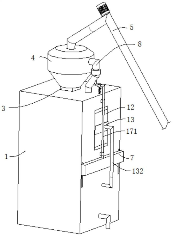
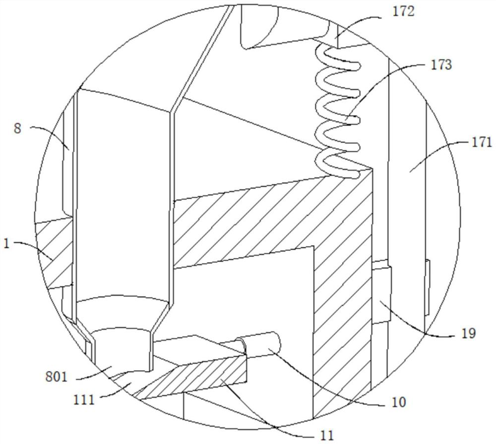
[0039] refer to figure 1 , figure 2 and Figure 4 , a water conservancy project dredging device, comprising a filter box 1, the filter box 1 is provided with an inclined filter screen plate 2, the top of the filter box 1 is connected with a connecting pipe 3, and the connecting pipe 3 is connected with a buffer shell 4, One end of the buffer casing 4 away from the connecting pipe 3 is connected with a sludge suction pipe 5, a pump body is arranged on the sludge suction pipe 5, a sludge outlet 301 is opened at the bottom of the connection pipe 3, and a sludge discharge port 301 is provided in the filter box 1 for plugging and discharging sludge. The floating component of the port 301, the filter box 1 is provided with a clamping component for restricting the movement of the floating component, the filter box 1 is provided with a silt discharge port 6, and the silt discharge port 6 is placed at the bottom end of the screen plate 2, and the silt discharge port A baffle plate 7...


PUM


Abstract

The invention discloses a hydraulic engineering desilting device and method, and belongs to the technical field of hydraulic engineering. A hydraulic engineering desilting device comprises a filter box, an obliquely-arranged filter screen plate is arranged in the filter box, the top of the filter box is connected with a connecting pipe, the connecting pipe communicates with a temporary storage shell, the end, away from the connecting pipe, of the temporary storage shell is connected with a silt pumping pipe, a pump body is arranged on the silt pumping pipe, and a silt outlet is formed in the bottom of the connecting pipe; a silt outlet is formed in the filter box, a floating assembly used for blocking the silt outlet is arranged in the filter box, a clamping assembly used for limiting movement of the floating assembly is arranged in the filter box, a silt discharging opening is formed in the filter box, the silt discharging opening is formed in the bottom end of the filter screen plate, a baffle is movably connected to the silt discharging opening, and a sewage discharging assembly is arranged on the filter box; while the river sludge cleaning efficiency is guaranteed, sludge and sewage are effectively separated, later sludge cleaning and transportation are facilitated, the possibility of secondary pollution to the surrounding environment in the transportation process is prevented, the working efficiency is improved, and the labor cost is saved.

Description

technical field [0001] The invention relates to the technical field of water conservancy projects, in particular to a silt removal device and a silt removal method for water conservancy projects. Background technique [0002] Water conservancy projects are used to control and allocate natural surface water and groundwater, and are also called water projects. Water is an indispensable and precious resource for human production and life, but its natural state does not fully meet human needs. The construction of water conservancy projects can control water flow, prevent flood disasters, regulate and distribute surface water and groundwater, and meet the needs of people's living and production. Water conservancy projects usually require the use of dredging devices to remove impurities such as silt in pipelines, inspection wells or river channels. [0003] In the prior art, a Chinese invention with a patent number of CN202111406766.6 discloses a water conservancy project dredgi...

Claims


Application Information

Patent Timeline
Patent Type & Authority Applications(China)
IPC IPC(8): B01D29/01B01D29/92B01D29/94E02F5/28E02F3/88E02F3/90
CPCB01D29/01B01D29/92B01D29/94E02F5/28E02F3/88E02F3/90
Inventor 尼旭东赵士滨王宗岳
Owner 珠海市厚江疏浚工程有限公司
Learn More