Massaging rehabilitation equipment for neurosurgery department
A kind of rehabilitation equipment and neurosurgery technology, which is applied in the field of medical equipment, can solve problems such as cervical spine massage for difficult patients, and achieve the effect of enhancing massage effect and enhancing practicability
- Summary
- Abstract
- Description
- Claims
- Application Information
AI Technical Summary
Problems solved by technology
Method used
Image
Examples
Embodiment 1
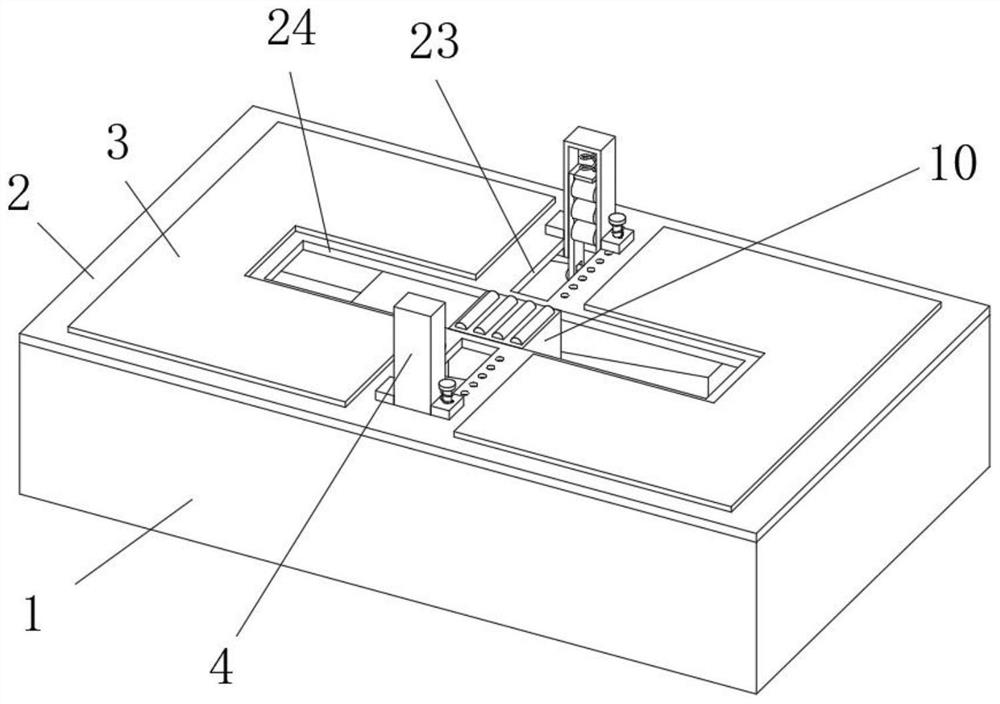
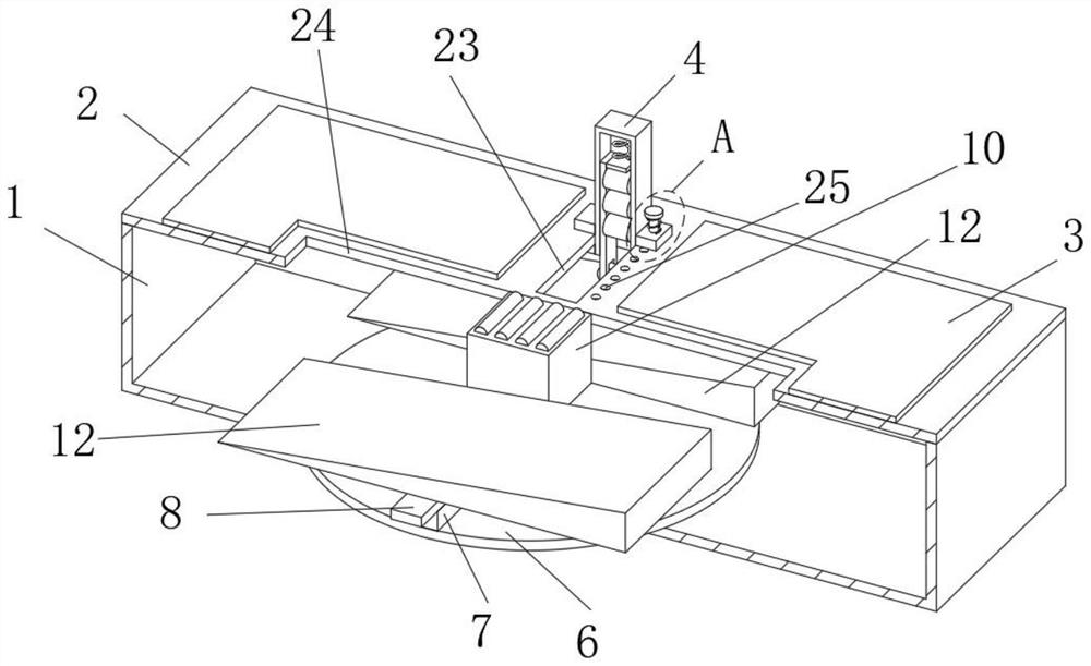
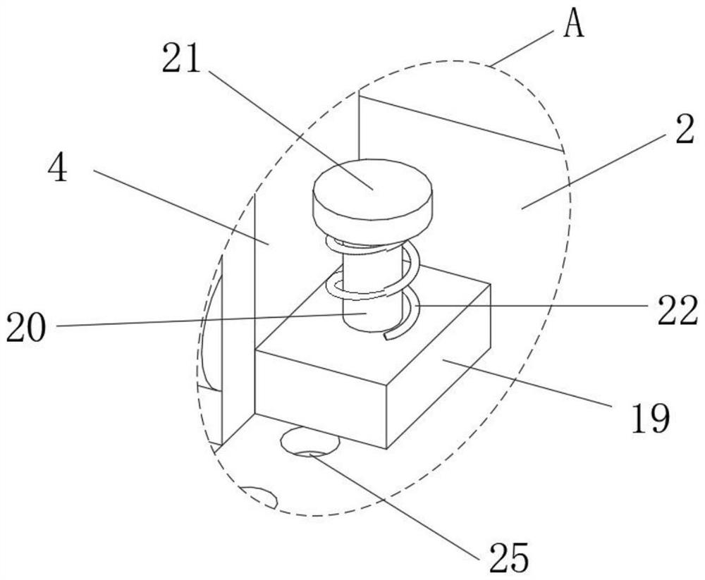
[0039] refer to Figure 1-6 The neurosurgical massage rehabilitation equipment shown includes a main casing 1, a top cover 2 is installed on the top of the main casing 1, a main sliding hole 24 is opened on the top of the top cover 2, and a mounting hole 24 is slidably installed in the main sliding hole 24. The seat 10, the top of the mounting seat 10 is rotatably installed with a plurality of bottom massage heads 11, the top of the top cover 2 is symmetrically provided with two side sliding holes 23, the side sliding holes 23 are slidably installed with a mounting frame 4, and the inner side of the mounting frame 4 A moving plate 14 is slidably installed on the wall, a plurality of side massage heads 17 are rotatably installed on the side of the moving plate 14, a spring connecting plate 15 is installed on the top of the moving plate 14, and elastic elements are installed on the spring connecting plate 15. A drive mechanism for driving the moving plate 14 to move up and down ...
Embodiment 2
[0042] Based on the above Embodiment 1, the elastic element includes a telescopic spring 16 , the telescopic spring 16 is installed in the installation frame 4 , the bottom end of the telescopic spring 16 is connected with the top of the spring connecting plate 15 , and the top end of the telescopic spring 16 is connected with the top of the installation frame 4 . connected to the inner wall. The setting of the telescopic spring 16 provides the spring connecting plate 15 and the moving plate 14 with pressure from the top inner wall of the mounting frame 4, so that the bottom end of the moving plate 14 is kept in contact with the inclined surface of the pressing inclined block 12 to ensure that the moving plate The bottom end of the 14 will be pressed by the inclined surface of the pressing inclined block 12, so as to reciprocate up and down.
Embodiment 3
[0044] Based on the above-mentioned embodiment 1 or 2, the driving mechanism includes a driving motor 5, which is installed on the bottom inner wall of the main housing 1, a turntable 6 is installed on the top of the output shaft of the driving motor 5, and a cylindrical pin is eccentrically installed on the top of the turntable 6. 9. A guide sliding assembly is installed on the main casing 1 . Start the drive motor 5 to drive the cylindrical pin 9 to rotate through the turntable 6, squeeze the side wall of the guide rail 7, and drive the main mounting plate 8 to slide back and forth along the inner side wall of the main housing 1, so that the two squeezes on the top of the main mounting plate 8 The oblique pressing block 12 reciprocates, and then presses the moving plate 14 by pressing the slope of the oblique block 12 .
PUM
 Abstract
Description
Claims
Application Information
 - R&D Engineer
- R&D Manager
- IP Professional
- Industry Leading Data Capabilities
- Powerful AI technology
- Patent DNA Extraction
Browse by: Latest US Patents, China's latest patents, Technical Efficacy Thesaurus, Application Domain, Technology Topic, Popular Technical Reports.
© 2024 PatSnap. All rights reserved.Legal|Privacy policy|Modern Slavery Act Transparency Statement|Sitemap|About US| Contact US: help@patsnap.com


