Electrical impedance imaging system applied to chest detection

A technology of electrical impedance imaging and chest, which is applied in the fields of application, diagnostic recording/measurement, medical science, etc. It can solve the problems of expensive discharge electrodes, insufficient contact of electrodes, and negative impact on imaging quality, so as to achieve contact and ensure imaging effect and diagnostic results, the effect of avoiding diagnostic errors

Pending Publication Date: 2022-07-29
合肥诺和电子科技有限公司
View PDF0 Cites 0 Cited by
  • Summary
  • Abstract
  • Description
  • Claims
  • Application Information

AI Technical Summary

Problems solved by technology

[0003] Since the electrical impedance imaging technology is to place multiple electrodes in a certain arrangement to ensure the quality of the image, the placement of electrodes for different test targets must conform to a uniform pattern, so if the electrodes are directly placed on the surface of the test target by the operator, it is very difficult Difficulty in ensuring electrode arrangement consistent with pre-planned patterns, uniformity and consistency across different test targets, negatively impacting image quality and requiring significant time-consuming draining of electrodes before each test
[0004] Due to differences in the gender of the test target individual, it often occurs that the skin of the test chest cannot fully contact with some electrodes, or even gaps appear, resulting in some electrodes not in contact with the skin of the test chest, and some electrodes are not in good contact with the skin, resulting in electrode Some electrodes in the array cannot provide corresponding real electrical signals, which will inevitably affect the imaging effect and diagnostic results of the electrical impedance imaging system

Method used


Image

  • Electrical impedance imaging system applied to chest detection
  • Electrical impedance imaging system applied to chest detection
  • Electrical impedance imaging system applied to chest detection

Examples


Embodiment Construction

[0024] In order to make the technical means, creative features, goals and effects realized by the present invention easy to understand, the present invention will be further described below with reference to specific embodiments and accompanying drawings, but the following embodiments are only preferred embodiments of the present invention, not all of them. . Based on the examples in the implementation manner, other examples obtained by those skilled in the art without creative work shall fall within the protection scope of the present invention.

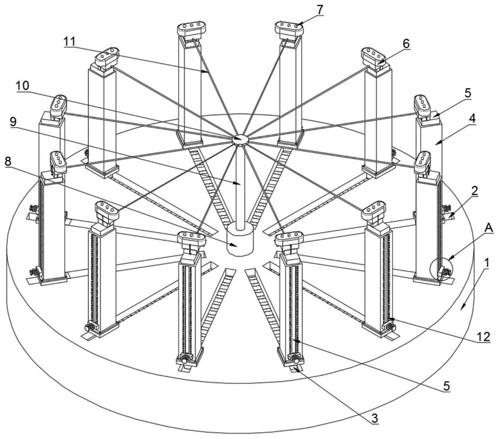
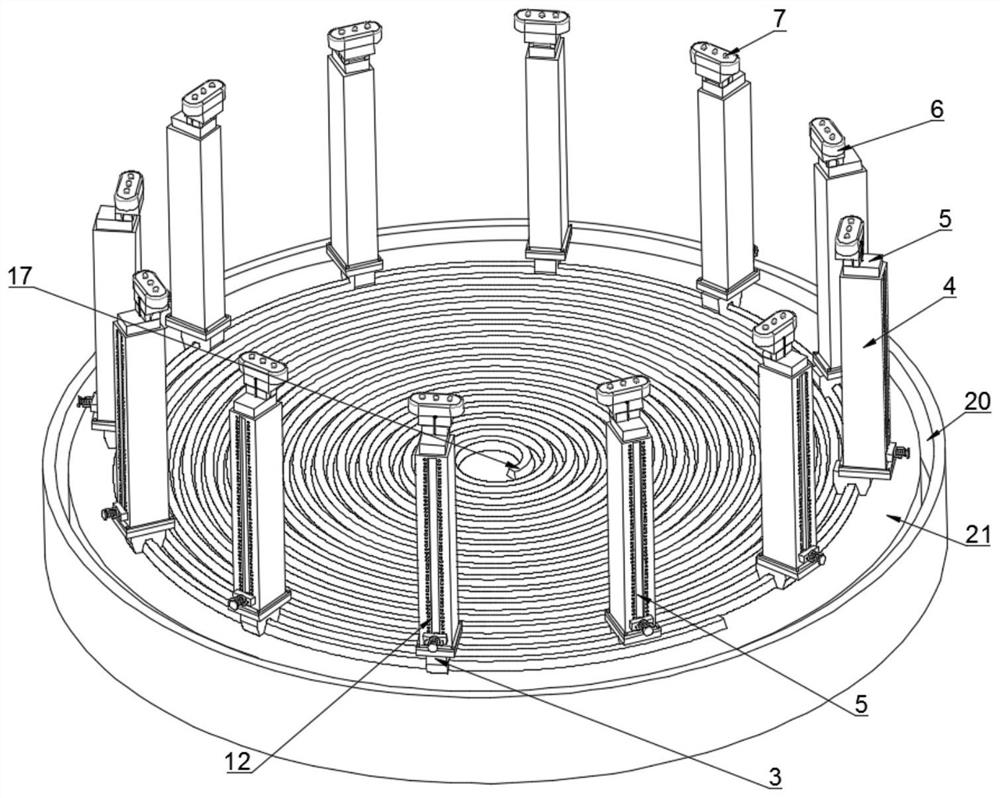
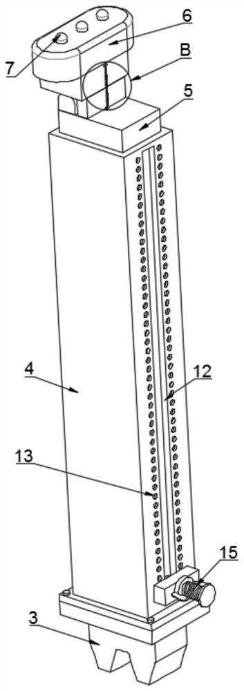
[0025] see Figure 1-5 , an electrical impedance imaging system applied to chest detection, comprising a support base 1 and an electrode mechanism arranged on the support base 1, the motor mechanism includes a plurality of lifting components arranged on the support base 1 and in a circular array, and a control unit A driving component for each lifting component to approach each other on the support base 1, and an electrode 7 arrang...


PUM


Abstract

The invention provides an electrical impedance imaging system applied to chest detection, which comprises a supporting seat and an electrode mechanism arranged on the supporting seat, the motor mechanism comprises a plurality of lifting assemblies which are arranged on the supporting seat and are arranged in a circumferential array, a driving assembly for controlling the lifting assemblies to get close to one another on the supporting seat, and electrodes arranged at the top ends of the lifting assemblies; the multiple electrodes are arranged at the top end of the lifting assembly through the mounting block, and the multiple electrodes are arranged on the mounting block at equal intervals; the mounting block is detachably connected with the lifting assembly; according to the invention, the electrodes can be uniformly and consistently placed on the chest of the measured target, so that the electrodes are fully contacted with the chest skin, and the imaging effect and the diagnosis result of the electrical impedance imaging system are ensured.

Description

technical field [0001] The invention relates to the technical field of electrical impedance imaging, in particular to an electrical impedance imaging system applied to chest detection. Background technique [0002] Because the electrical impedance characteristics of diseased tissue and normal biological tissue are significantly different, medical imaging techniques using the principle of bioimpedance, such as electrical impedance tomography (Electrical Impedance Tomography, EIT), electrical impedance spectroscopy (Electrical Impedance Spectroscopy, EIS), It can effectively detect and locate the diseased part of the organism. The medical imaging technology using the principle of bioimpedance detects the impedance distribution inside the organism by placing electrodes on the surface of the organism and injecting low-frequency low-power current, and detecting the voltage difference between the electrodes to detect the impedance distribution inside the organism. It can be detec...

Claims


Application Information

Patent Timeline
IPC IPC(8): A61B5/0536
CPCA61B5/0536
Inventor 刘久红
Owner 合肥诺和电子科技有限公司
Why Eureka
Try Eureka