Magnetic control induction control device

A technology of inductive control and magnetic induction, applied in the direction of logic circuits using specific components, can solve the problems of poor scalability and insufficient utilization, and achieve the effect of long service life, reasonable structure, and elimination of liquid entry.

Pending Publication Date: 2022-07-26
佛山市小为电器科技有限公司
View PDF0 Cites 0 Cited by
  • Summary
  • Abstract
  • Description
  • Claims
  • Application Information

AI Technical Summary

Problems solved by technology

However, in the existing technology, its application is mostly limited to single point and single function. Since the magnetic elements are sensitive to mutual interference, it is impossible to arrange multiple magnetic control elements compactly and adjacently to achieve multi-point, Multi-functional application scenarios lead to poor scalability, and only play a very small role in the entire control circuit, which cannot be fully utilized

Method used


Image

  • Magnetic control induction control device
  • Magnetic control induction control device
  • Magnetic control induction control device

Examples


Embodiment Construction

[0023] Below in conjunction with accompanying drawing and embodiment, the present invention is further described:

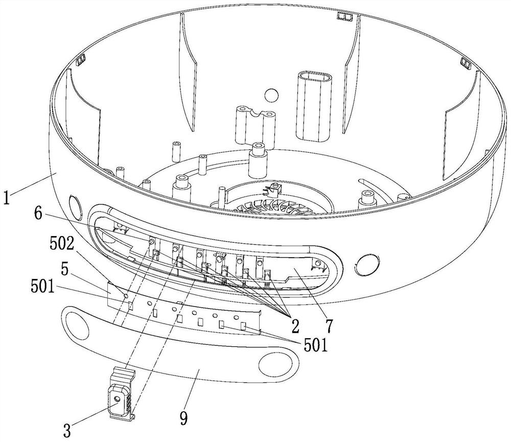
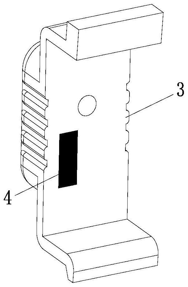
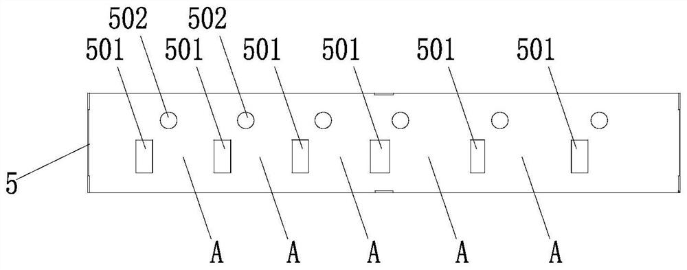
[0024] like Figure 1-Figure 6 Shown: a magnetic induction control device, comprising a body 1, a magnetic induction element 2 fixedly arranged on the body 1, and an adjusting body 3 movably arranged relative to the magnetic induction element 2, and a magnet 4 is installed on the adjusting body 3. When the magnet 4 passes through When the adjusting body 3 moves to be opposite to the magnetic induction element 2, the magnetic induction element 2 constitutes a trigger of the signal. The magnetic sheet 5 is provided with an induction through hole 501 suitable for the magnetic field lines or magnetic induction lines on the magnet 4 to pass through.

[0025] The difference between the magnetic induction control device using this structure and the prior art is that a magnetic isolation sheet 5 is arranged between the adjusting body 3 and the magnetic induction element...


PUM


Abstract

A magnetic control induction control device comprises a fixedly-arranged magnetic induction element and an adjusting body movably arranged relative to the magnetic induction element, a magnet is installed on the adjusting body, when the magnet moves to be opposite to the magnetic induction element through the adjusting body, the magnetic induction element triggers signals, a magnetic isolation sheet is arranged between the adjusting body and the magnetic induction element, and the magnetic isolation sheet is connected with the adjusting body. The magnetic isolation sheet corresponding to the orthographic projection direction of the magnetic induction element is provided with an induction through hole suitable for a magnetic line of force on the magnet to pass through. The structure is simple and reasonable, the advantages of magnetic control elements are reserved, two or more than two magnetic control elements can be randomly and adjacently arranged, different function requirements of products can be formulated, wider design and setting space is provided for circuit control and function setting, and due to the fact that the magnetic control mode belongs to a non-contact control structure, the magnetic control elements can be arranged in a non-contact mode. And the product modeling has more creative space.

Description

technical field [0001] The invention relates to the technical field of magnetron induction, in particular to a magnetron induction control device. Background technique [0002] At present, it is a common technical means to use magnetron elements, such as reed switches, Hall elements and other sensors to realize the connection or disconnection of control circuits. The control switch has a much simpler structure and a longer service life. However, in the prior art, most of its applications are limited to a single point and a single function. Since the magnetic elements are sensitive to mutual interference, it is impossible to compactly arrange multiple magnetron elements together to achieve multi-point, Multi-functional application scenarios lead to poor scalability, only play a very small role in the entire control circuit, and cannot be fully utilized. SUMMARY OF THE INVENTION [0003] The purpose of the present invention is to overcome the deficiencies in the above-ment...

Claims


Application Information

Patent Timeline
Patent Type & Authority Applications(China)
IPC IPC(8): H03K19/02
CPCH03K19/02
Inventor 王成斌莫奕田简炳根黎伟文陈土炎
Owner 佛山市小为电器科技有限公司
Why Eureka
Try Eureka