Binder retention implant standle for

A technology of implants and osseointegrating agents, used in bone implants, joint implants, joint implants, etc.

Pending Publication Date: 2022-07-22
WALDEMAR LINK GMBH & CO
View PDF0 Cites 0 Cited by
  • Summary
  • Abstract
  • Description
  • Claims
  • Application Information

AI Technical Summary

Problems solved by technology

In such cases, even the combined implant stem technique often proves to be less reliable and stable than desired

Method used


Image

  • Binder retention implant standle for
  • Binder retention implant standle for
  • Binder retention implant standle for

Examples


Embodiment Construction

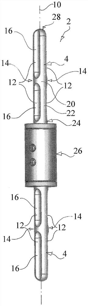
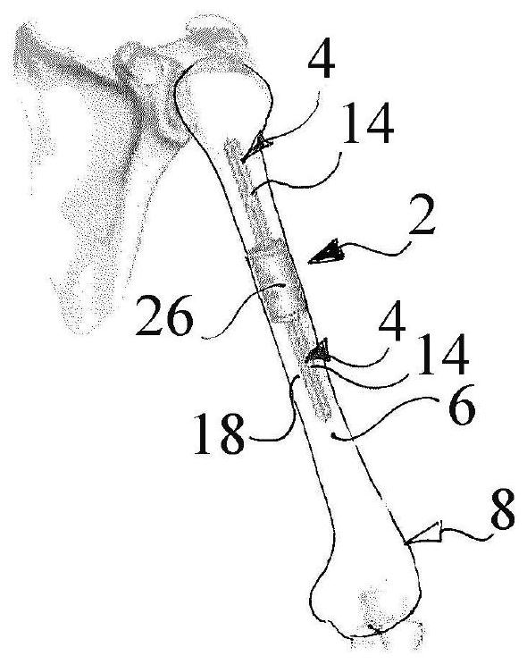
[0028] Figure 1 to Figure 3 An implant 2 (i.e. a diaphyseal segment prosthesis 2) is shown comprising two stems 4 adapted to be implanted in conjunction with the medullary cavity 6 of a long bone, and in particular a human humerus 8 ( After preparing cavity 6 by surgery). The implant 2 has a longitudinal axis 10 .

[0029] In this exemplary embodiment, each of the shanks 4 includes two recesses 12 in the circumferential direction of the shank 4 . Nonetheless, any number of recesses 12 may be formed in the aforementioned circumferential direction. The same applies to the aforementioned dimensions and shapes of the recesses 12 .

[0030] In this exemplary embodiment, the recesses are formed as grooves, ie elongated recesses. As shown, they may be positioned parallel to each other, on opposite sides of the shank, and / or extend in the direction of or along the longitudinal axis 10 .

[0031] Each recess 12 is blocked in the longitudinal direction of the shank 4 by an obstacl...


PUM

PropertyMeasurementUnit
Minimum widthaaaaaaaaaa

Abstract

The invention relates to a handle (4) for an implant (2) or a handle (4) of an implant (2), having a longitudinal axis (10) and at least one recess (12), the handle (4) being adapted to be incorporated into implantation into a medullary cavity (6) and / or into a cavity (6) created by surgery of a long bone (8), characterized in that the recess is blocked by an obstacle (14). Furthermore, the invention relates to a method for preparing a stem (4) of an implant (2) according to any of the preceding claims for implantation, comprising the step of placing a binding agent (16) in recesses (12) on both sides of an obstacle (14).

Description

technical field [0001] The present disclosure relates to implant stems including recesses blocked by obstacles and methods for preparing such implant stems for implantation. Background technique [0002] An important goal in orthopaedic surgery is the reliable anchoring of the implant within the bone. For implantation into long bones, implant stems are widely used as the primary design element for bone anchoring in various implants. For these implant stems, it is a common technique to anchor the implant stem within the medullary canal of a long bone using a bonding agent. An alternative technique is to use a non-bonded implant stem that is first anchored during surgery by a press fit and configured so that bone tissue can grow into the surface structure of the stem, thereby passing the bone to the surface. Ingrowth produces secondary fixation of the stalk. However, the present invention relates to stems for bonding implants. [0003] In particular, high-risk patients, su...

Claims


Application Information

Patent Timeline
IPC IPC(8): A61F2/36A61B17/72A61F2/40A61F2/38A61F2/30A61F2/46A61F2/28
CPCA61F2002/3082A61F2002/30827A61F2/3804A61F2002/30329A61F2002/30604A61F2220/0025A61F2002/30224A61F2230/0069A61F2002/30405A61F2002/30433A61F2220/0041A61F2/28A61B17/7233A61F2002/2825A61F2002/30354A61F2002/2853A61B17/72A61B17/88
Inventor 赫尔穆特·D·林克鲁道夫·卡帕纳
Owner WALDEMAR LINK GMBH & CO
Why Eureka
Try Eureka