Eureka AIR delivers breakthrough ideas for toughest innovation challenges, trusted by R&D personnel around the world.

Beam-pumping unit crank position detection system and method

A beam pumping unit and detection system technology, which is applied to liquid variable capacity machinery, pump testing, mechanical equipment, etc. The effect of high pollution level, strong tolerance and strong adaptability

Pending Publication Date: 2022-07-22
SHENYANG ZHONGKE AOWEI SCI & TECH CO LTD
View PDF0 Cites 0 Cited by
  • Summary
  • Abstract
  • Description
  • Claims
  • Application Information

AI Technical Summary

Problems solved by technology

[0002] Most of the conventional position encoders used in oil fields are integrated photoelectric position detection encoders, and a small part are integrated resolver position detection encoders. In general, integrated encoders have high requirements for installation process and installation position. And its expensive unit price is not suitable for large-area and large-scale use
At present, most of the existing domestic oilfield pumping units are already in the state of mass production of crude oil. The installation of conventional encoders for position detection requires a certain degree of modification of the physical structure of the original pumping units to meet the needs of encoder installation. The material cost and personnel cost of the pumping unit are relatively high, and the transformation effect is not high

Method used

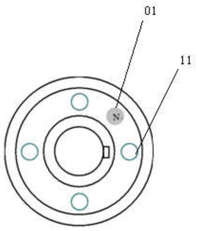
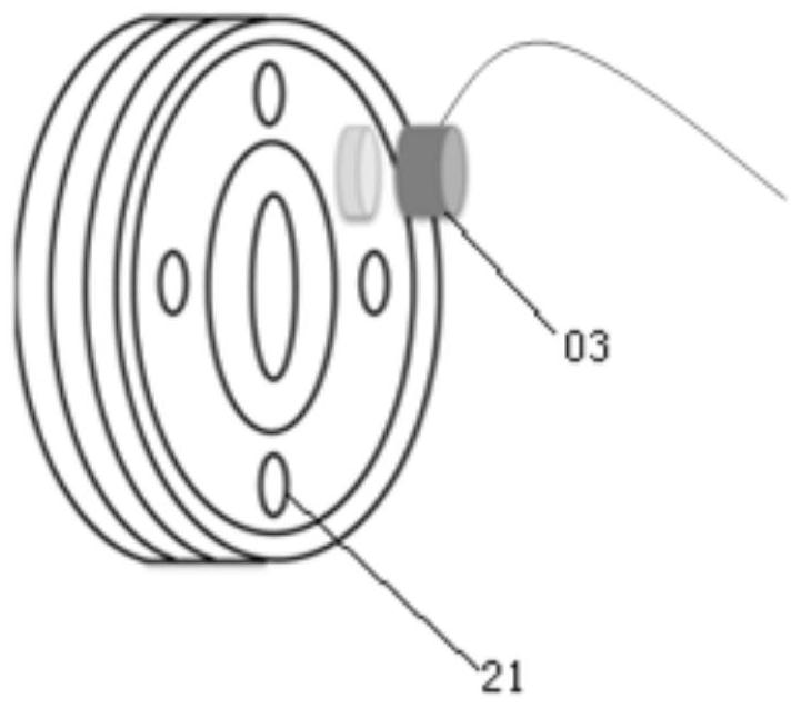

Image

  • Beam-pumping unit crank position detection system and method
  • Beam-pumping unit crank position detection system and method
  • Beam-pumping unit crank position detection system and method

Examples


Embodiment Construction

[0047] The present invention will be further described in detail below with reference to the accompanying drawings and embodiments.

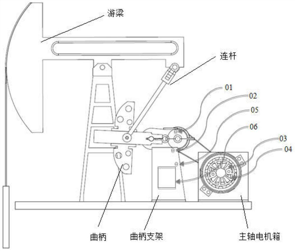
[0048] like figure 1 As shown, it is a schematic structural diagram of the crank position detection system in the beam pumping unit area of ​​the present invention. The present invention includes: a first position sensor, a second position sensor, a crank position sensor 05 and a position signal detection processing unit 06;

[0049] The first position sensor is located at the reduction box of the pumping unit, and is connected to the position signal detection processing unit 06, for sending out the position signal pulse of the pulley of the reduction box, and collected by the position signal detection processing unit 06;

[0050] The second position sensor is arranged at the pulley on the motor main shaft for controlling the swing of the beam of the pumping unit, and is connected to the position signal detection processing unit 06 for sending o...


PUM


Abstract

The invention belongs to the field of oil pumping unit crank position detection, and particularly relates to a beam-pumping unit crank position detection system and method, and the system comprises a position signal detection processing unit, and a first position sensor, a second position sensor and a crank position sensor which are connected with the position signal detection processing unit; the first position sensor is arranged at a reduction gearbox of the oil pumping unit; the second position sensor is arranged on a belt pulley on a motor main shaft for controlling the pumping unit walking beam to swing; the crank position sensor is fixedly arranged on a crank bracket of the oil pumping unit; and the position signal detection processing unit is used for receiving and processing the reduction gearbox belt pulley position signal pulse, the motor main shaft belt pulley position signal pulse and the crank position pulse signal of the first position sensor, the second position sensor and the crank position sensor, and obtaining oil pumping unit belt fault pre-diagnosis information. According to the position sensor, a split structure is adopted, and the current crank position information can be detected more quickly on the premise that equipment is slightly modified.

Description

technical field [0001] The invention belongs to the field of crank position detection of pumping units, in particular to a crank position detection system and method of a beam-type pumping unit. Background technique [0002] The conventional position encoders used in oil fields are mostly integrated photoelectric position detection encoders, and a small part of integrated resolver position detection encoders. Generally, integrated encoders have higher requirements on installation technology and installation position. And its unit price is expensive and it is not suitable for large-scale use. At present, most of the existing oilfield pumping units in China are already in the state of mass production of crude oil. To install a conventional encoder to detect its position requires a certain degree of transformation of the physical structure of the original pumping unit to meet the needs of encoder installation. The material cost and personnel cost of the pumping unit are relati...

Claims


Application Information

Patent Timeline
Patent Type & Authority Applications(China)
IPC IPC(8): E21B47/009F04B51/00F04B49/10
CPCE21B47/009F04B51/00F04B49/10
Inventor 许世鹏李金英张雨田赵雪峰
Owner SHENYANG ZHONGKE AOWEI SCI & TECH CO LTD
Why Eureka
Eureka Blog
Learn More