Casement window hinge, manufacturing method of casement window hinge, and casement window using casement window hinge

A casement window and hinge technology, which is applied in the casement window hinge and its manufacturing field, can solve the problems of reduced bearing capacity of slide rails, low dimensional accuracy requirements, and falling off of stamping parts, and achieves fast positioning and assembly, and improves production efficiency. The effect of increasing the fixed strength

Active Publication Date: 2017-12-22
LIP HING YEUNG S IND (SHENZHEN) CO LTD
View PDF6 Cites 7 Cited by
  • Summary
  • Abstract
  • Description
  • Claims
  • Application Information

AI Technical Summary

Problems solved by technology

However, in the production process, since the dimensional accuracy of the pull rod 3 is not high, there is no strict requirement on the angle of the tip of the triangle during manufacture, so some products appear. In the process of closing the pull rod 3 and the slide rail 1, The edge of the triangle point scrapes against the edge of the vertical plane of the hinge fixing part 7, so that the pull rod 3 cannot be completely closed, which affects the use
[0005] The traditional manufacturing method of the fixed part of the hinge is to first open a hole on the horizontal plane of the fixed part of the hinge, and then punch a part of the bottom surface of the slide rail into the hole through a punching machine, but this method will destroy the mechanical structure of the slide rail, As a result, the bearing capacity of the slide rail is reduced, and after tens of thousands of opening and closing of the window hinge, the vibration of the slide rail may cause the punched part to fall out of the hole, resulting in the window hinge being unusable

Method used


Image

  • Casement window hinge, manufacturing method of casement window hinge, and casement window using casement window hinge
  • Casement window hinge, manufacturing method of casement window hinge, and casement window using casement window hinge
  • Casement window hinge, manufacturing method of casement window hinge, and casement window using casement window hinge

Examples


Embodiment Construction

[0041] In order to further illustrate the technical means adopted by the present invention and its effects, the following describes in detail in conjunction with preferred embodiments of the present invention and accompanying drawings.

[0042] The specific embodiment of the present invention provides a casement window hinge.

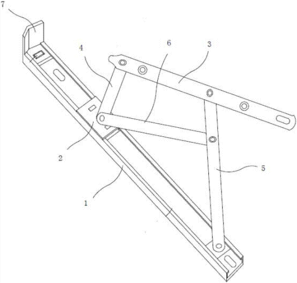
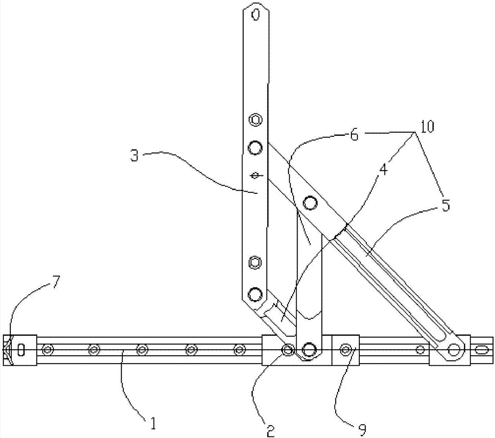
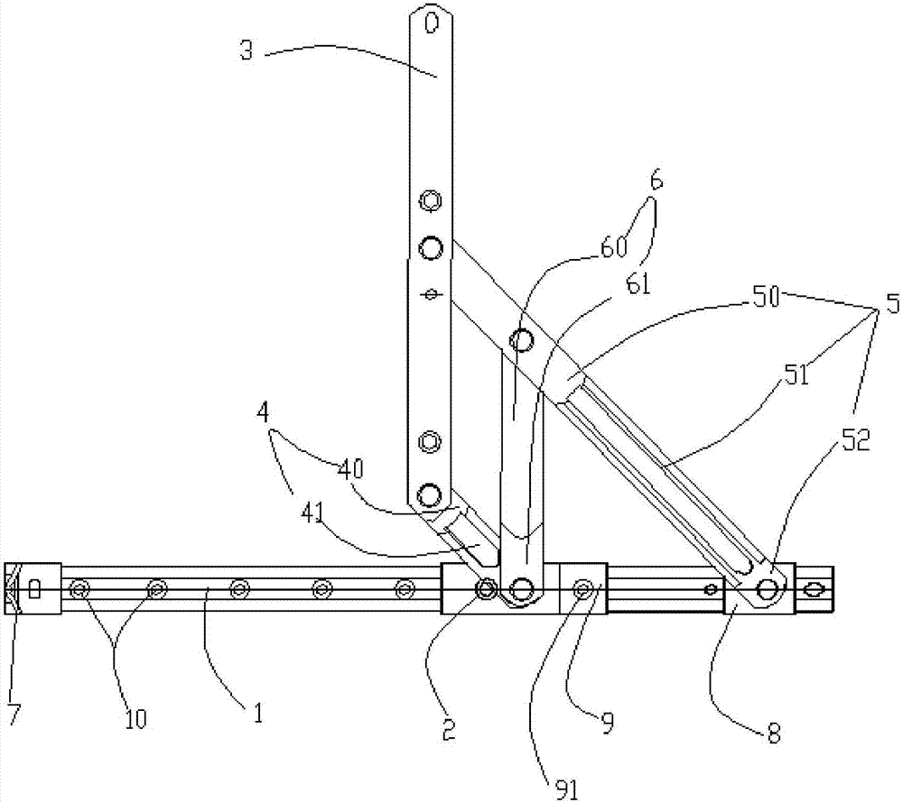
[0043] Please refer to figure 2 , the casement window hinge includes a slide rail 1 , a pull rod 3 , a hinge fixing part 7 , a sliding part 2 and a connecting part 10 .

[0044] Described slide rail 1 is fixed on the bottom window frame of form, is generally fixed by screw. The slide rail 1 has a sliding groove 13 along the extending direction of the slide rail; wherein, a hinge fixing part 7 is fixed at one end of the slide rail 1; The sliding part 2 is fixed on the sliding rail 1 and can slide on the sliding rail 1 .

[0045] The pull rod 3 is rotationally fixed on the sliding part 2 through the connecting part 10, and when the sliding part 2 slid...


PUM


Abstract

The invention discloses a casement window hinge. The casement window hinge comprises a slide rail, a pull rod, a hinge fixing part fixed to one end of the slide rail, and a sliding part installed in the slide rail and capable of sliding; the pull rod is fixed to the sliding part through a connecting part; the pull rod makes the angular movement relative to the slide rail when the sliding part slides; when the pull rod and the slide rail are in a closed state, one end of the pull rod abuts against the hinge fixing part; the slide rail comprises a first groove and a second groove which are in perpendicular intersection; the hinge fixing part comprises a corner wrapping end, a connecting end and a fixing end; the corner wrapping end and the fixing end are connected by the connecting end; the corner wrapping end and the fixing end are perpendicular to each other; the connecting end is contained in the first groove; the fixing end is installed in the second groove; and the casement window hinge further comprises a limiting block which is fixed to the slide rail and used for fixing the fixing end, and therefore the fixing strength of the hinge fixing part fixed to the slide rail is improved.

Description

technical field [0001] The invention relates to a hinge structure and a manufacturing method thereof, in particular to a casement window hinge and a manufacturing method thereof. Background technique [0002] The casement window has the advantages of large opening area, good ventilation, good sealing, sound insulation, heat preservation, and impermeability, and is deeply loved by the public. The inward opening type is convenient for cleaning the window; the outward opening type does not take up space when opening. . [0003] see figure 1 A common casement window hinge includes a slide rail 1 fixed on the window frame, a pull rod 3 fixed on the sash, a sliding part 2 installed in the slide rail 1 and slidable, and one end is rotatably fixed on the sliding part 2 The other end is rotatably fixed to the first connecting plate 4 at one end of the pull rod 3, one end is rotatably fixed to the end of the slide rail 1, the other end is rotatably fixed to the second connecting pla...

Claims


Application Information

Patent Timeline
Patent Type & Authority Applications(China)
IPC IPC(8): E05D3/06E05D11/10B23P15/00
CPCB23P15/00E05D3/06E05D11/10
Inventor 杨钟汉
Owner LIP HING YEUNG S IND (SHENZHEN) CO LTD
Why Eureka
Try Eureka