Eureka AIR delivers breakthrough ideas for toughest innovation challenges, trusted by R&D personnel around the world.

Mercury, sulfur and carbon synergistic and integrated removal dust removal system

A dust removal system, sulfur carbon technology, applied in the fields of sulfur compounds, solid separation, inorganic chemistry, etc., can solve the problems of complex process, large area and high cost, and ensure the emission of particulate matter at the outlet, low cost and small area. Effect

Pending Publication Date: 2022-07-22
浙江菲达环保科技股份有限公司
View PDF2 Cites 0 Cited by
  • Summary
  • Abstract
  • Description
  • Claims
  • Application Information

AI Technical Summary

Problems solved by technology

Existing synergistic removal equipment mostly adopts dust removal + SO removal 3 + Mercury removal + CCUS, the process is complex, the cost is high, and the floor area is large. Therefore, a dust removal system for the coordinated and integrated removal of mercury, sulfur and carbon is proposed

Method used


Image

  • Mercury, sulfur and carbon synergistic and integrated removal dust removal system
  • Mercury, sulfur and carbon synergistic and integrated removal dust removal system

Examples


Embodiment 1

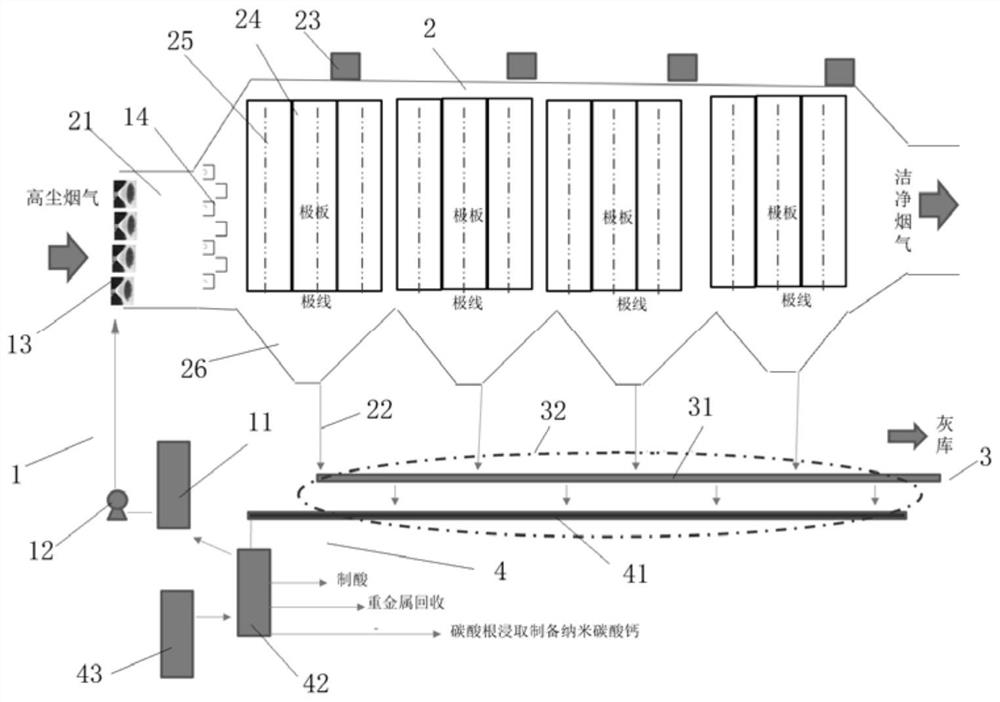
[0017] see figure 1 , the present invention is a dedusting system for the integrated removal of mercury, sulfur and carbon, including an absorbent injection system 1, a dust removal system 2, an ash conveying system 3 and a magnetic adsorbent recycling system 4. The absorbent injection system 1 is on the Several dry powder spray guns 13 are provided, and the dry powder spray guns 13 are installed in the inlet flue 21 of the dust removal system 2. The ash conveying system 3 includes an ash conveying mechanism 31 and a magnetic separation device 32 (not shown in the figure). The ash discharge port of the dust removal system 2 is connected to the inlet of the ash conveying mechanism 31, the magnetic separation device 32 is used to magnetically select the magnetic adsorbent in the fly ash conveyed by the ash conveying mechanism 31, and the outlet of the magnetic separation device 32 It is connected to the inlet of the magnetic adsorbent recycling system 4 , and the outlet of the m...

Embodiment 2

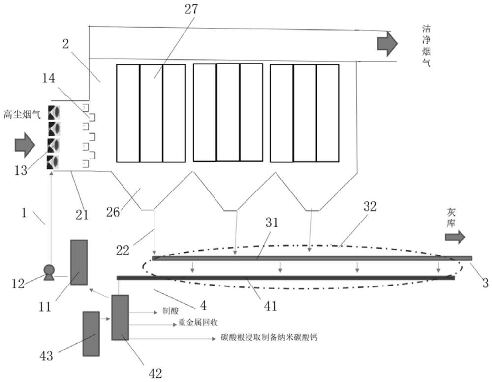
[0028] see figure 2 The difference between this embodiment and Embodiment 1 is that the dust collector is a bag type dust collector, including a body, a cage, a cloth bag 27, a top-level airflow uniform distribution, a backflushing system, an ash hopper 26, and the like.

[0029] The working process of the present invention:

[0030] Through the absorbent injection system 1, the magnetic mercury-sulfur-carbon adsorbent can be uniformly injected into the inlet flues 21 of all levels of electric fields. The adsorbent is fully mixed with the flue gas, and the adsorbent after absorbing pollutants is collected by the bag filter and collected in the ash hopper 26, and the adsorbent stays on the surface of the bag 27 for a long time, and the adsorption and removal effect is better than that of the electrostatic precipitator. Good; before the fly ash is transported to the ash warehouse via the ash conveying mechanism 31, the magnetic adsorbent mixed in the ash is magnetically separa...


PUM

PropertyMeasurementUnit
particle diameteraaaaaaaaaa

Abstract

The invention discloses a mercury-sulfur-carbon synergetic integrated removal dust removal system, which comprises an absorbent injection system, a dust removal system, an ash conveying system and a magnetic adsorbent recovery and reuse system, a plurality of dry powder spray guns are arranged on the absorbent injection system, the dry powder spray guns are arranged in an inlet flue of the dust removal system, and the magnetic adsorbent recovery and reuse system is arranged on the dust removal system. The ash conveying system comprises an ash conveying mechanism and a magnetic separation device, an ash discharge port of the dust removal system is connected with an inlet of the ash conveying mechanism, the magnetic separation device is used for magnetically separating out a magnetic adsorbent in fly ash conveyed by the ash conveying mechanism, and an outlet of the magnetic separation device is connected with an inlet of the magnetic adsorbent recycling system. And an outlet of the magnetic adsorbent recycling system is connected to the absorbent injection system. The system can realize integrated removal of dust, sulfur, mercury and carbon, and is small in occupied area, low in cost and more suitable for large-scale engineering popularization.

Description

【Technical field】 [0001] The invention relates to the technical field of pollutant treatment, in particular to the technical field of a dust removal system for the coordinated and integrated removal of mercury, sulfur and carbon. 【Background technique】 [0002] With the rapid development of my country's economy and society, energy and environmental problems have become increasingly prominent. my country's coal-based energy pattern will not change significantly for a long period of time, and the flue gas generated by coal-fired power plants contains a variety of gaseous or solid pollutants, such as SO 2 , NO x , Hg and PM10 or PM2.5 particles with particle size less than 20μm or 2.5μm, etc., although CO 2 It has not been included in the control object of air pollutants, but it has received increasing attention due to its greenhouse effect, and power plants are the largest CO 2 One of the stationary emission sources. The existing synergistic removal equipment mostly adopts...

Claims


Application Information

Patent Timeline
Patent Type & Authority Applications(China)
IPC IPC(8): B01D53/06B01D46/02B01D50/00B03C3/013B03C3/017B03C3/04C01B17/74C01F11/18
CPCB01D53/06B01D46/023B01D50/00B03C3/013B03C3/017B03C3/04C01F11/18C01B17/74B01D2258/0283B01D2257/302B01D2257/602B01D2259/40001B01D2257/504B01D2259/40083
Inventor 刘含笑吴黎明赵琳胡运进崔盈何毓忠于立元周号王帅
Owner 浙江菲达环保科技股份有限公司
Why Eureka
Eureka Blog
Learn More