
Lower vehicle body front structure

A technology of structural main body and front wheel, applied in the direction of substructure, superstructure, vehicle parts, etc., can solve the problems that the energy absorption and buffering effect cannot be fully exerted, the torsional impact damage of the front longitudinal beam of the engine room, and the destruction of the car body skeleton structure, etc. To achieve the effect of improving collision protection performance, good cushioning effect and improving structural strength

Pending Publication Date: 2022-07-19
GREAT WALL MOTOR CO LTD
View PDF8 Cites 0 Cited by
  • Summary
  • Abstract
  • Description
  • Claims
  • Application Information

AI Technical Summary

Problems solved by technology

The energy-absorbing and buffering effect of the front anti-collision beam energy-absorbing box connecting the bracket and the front anti-collision beam bracket is difficult to be fully exerted
When the impact force reaches the end of the front longitudinal beam of the engine room, it will cause huge torsional impact damage to the front longitudinal beam of the engine room, which may destroy the entire body frame structure at the front cabin, and cause damage to the components in the front cabin, and even Occupants in the cockpit inflicted impact damage

Method used

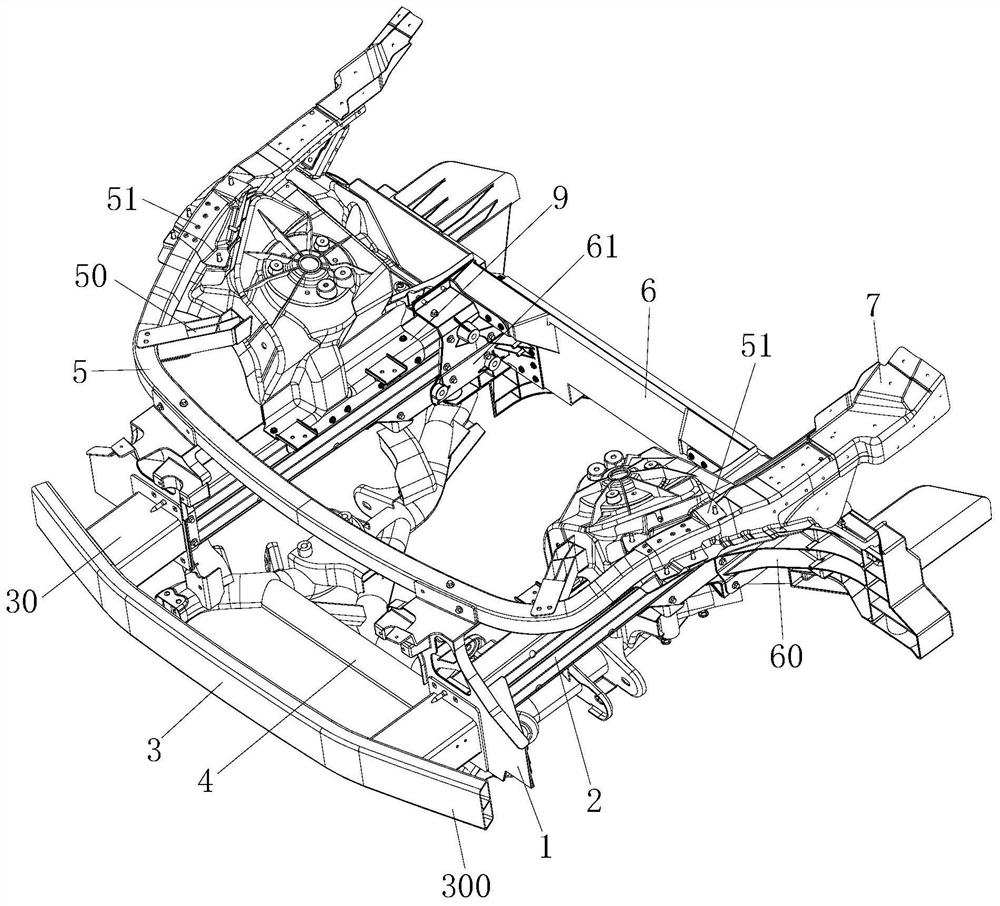

Image

  • Lower vehicle body front structure
  • Lower vehicle body front structure
  • Lower vehicle body front structure

Examples


Embodiment Construction

[0054] It should be noted that the embodiments of the present invention and the features of the embodiments may be combined with each other under the condition of no conflict.

[0055] In the description of the present invention, it should be noted that if terms such as "upper", "lower", "inside", and "back" appear to indicate orientation or positional relationship, they are based on the orientation or positional relationship shown in the accompanying drawings. , is only for the convenience of describing the present invention and simplifying the description, rather than indicating or implying that the indicated device or element must have a specific orientation, be constructed and operated in a specific orientation, and therefore cannot be construed as a limitation of the present invention; Terms such as "one" and "second" are also used for descriptive purposes only and should not be construed to indicate or imply relative importance.

[0056] In addition, in the description o...


PUM


Abstract

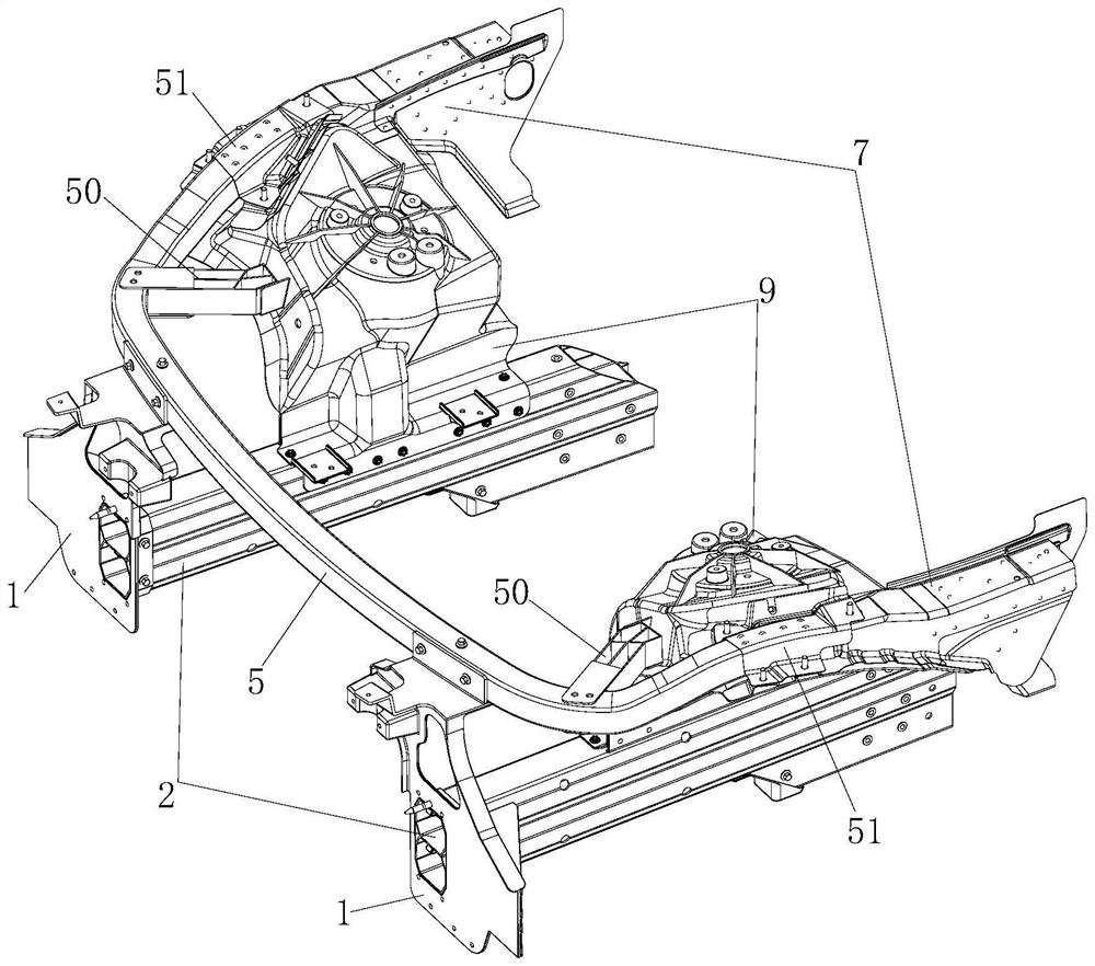
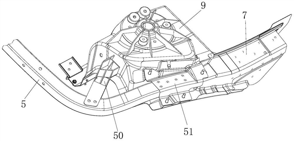
The invention provides a front structure of a lower vehicle body. The front structure comprises cabin front longitudinal beams arranged on the two sides respectively, a front anti-collision beam connected between the front ends of the cabin front longitudinal beams on the two sides, and a cabin rear cross beam connected between the rear ends of the cabin front longitudinal beams on the two sides. And the cabin front longitudinal beams on the two sides are respectively connected with a front shock absorber seat. The front ends of the cabin front longitudinal beams on the two sides are connected with the front anti-collision beam assembly through connecting bases, and the connecting bases are provided with energy absorption parts. Front wheel cover edge beams are connected to the outer sides of the front shock absorber seats on the two sides respectively, a front cabin upper cross beam is connected between the front wheel cover edge beams on the two sides, the front cabin upper cross beam is arched out towards the front of the vehicle body, and front cabin upper cross beam energy absorption boxes are connected between the front cabin upper cross beam and the front shock absorber seats on the two sides respectively. The extending section of the front anti-collision beam, the energy absorption part and the front cabin upper cross beam energy absorption box are sequentially arranged in the direction pointing to the rear portion of the vehicle body. According to the lower vehicle body front structure, the collision protection performance of the front portion of the vehicle body can be improved.

Description

technical field [0001] The invention relates to the technical field of automobile body structures, in particular to a lower body front structure. Background technique [0002] In the design of the body frame of the front cabin of an automobile, safety and lightweight design are important issues that affect each other and need to be considered. [0003] In the structure of the front cabin body frame, the front anti-collision beam is mainly used to receive the collision from the front of the vehicle. The front anti-collision beam is generally connected to the front longitudinal beam of the cabin through structures such as the front anti-collision beam energy-absorbing box and the connecting bracket; the front anti-collision beam The received collision impact force is transmitted to the front longitudinal beam of the cabin along the path of the front crash beam, the energy absorption box of the front crash beam and the connecting bracket. The front anti-collision beam and the ...

Claims


Application Information

Patent Timeline
Patent Type & Authority Applications(China)
IPC IPC(8): B62D21/02B62D21/15B62D21/11B60R19/34B62D29/00B60K11/00
CPCB62D21/02B62D21/152B62D21/157B62D21/11B60R19/34B62D29/008B60K11/00B62D25/082
Inventor 陈强贺志杰张涛张书任梁新宇武文波李任李运涛
Owner GREAT WALL MOTOR CO LTD
Learn More