
High-strength protection device for high-voltage electric power

A technology of high-voltage power and protection devices, which is applied in the field of high-strength protection devices for high-voltage power, can solve the problems of cable accidents that cannot provide good protection, cables swinging from side to side, power supply safety hazards, etc., to ensure the protection effect of impurity removal , Guarantee the effect of stability and safety

Pending Publication Date: 2022-07-15
江苏元本电力技术有限公司
View PDF0 Cites 0 Cited by
  • Summary
  • Abstract
  • Description
  • Claims
  • Application Information

AI Technical Summary

Problems solved by technology

[0003] High-voltage cables are usually installed at high altitudes, and the cables between two utility poles droop in an arc shape. In case of strong winds, the cables will sway from side to side, which brings hidden dangers to the safety of power supply. The existing high-strength protection devices for high-voltage power are generally It only plays the role of temporary support, and it cannot protect the cable from temporary accidents. Therefore, it is necessary to study a multifunctional high-strength protection device for high-voltage power.

Method used


Image

  • High-strength protection device for high-voltage electric power
  • High-strength protection device for high-voltage electric power
  • High-strength protection device for high-voltage electric power

Examples


Embodiment 1

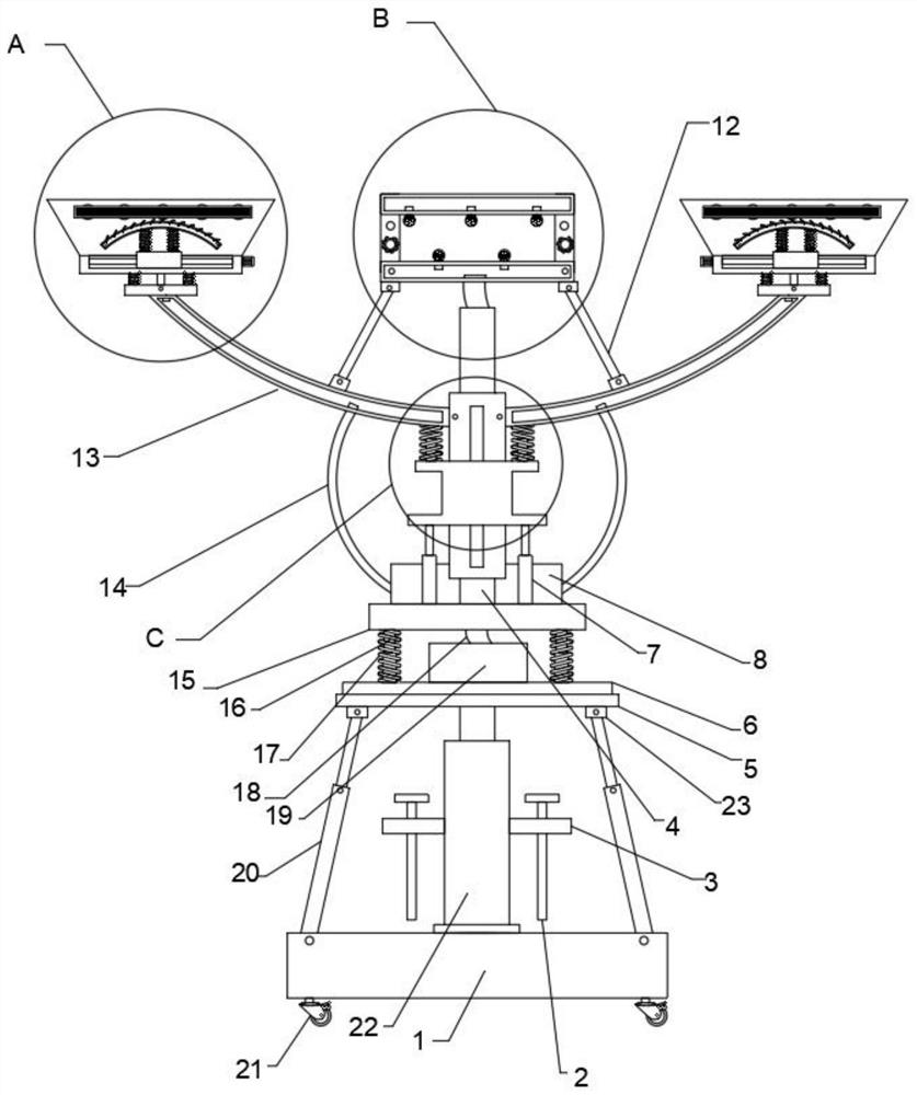
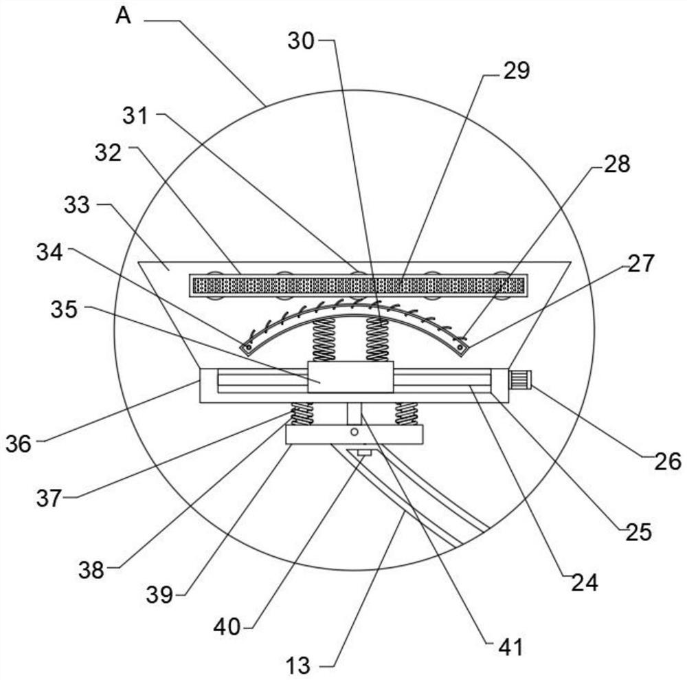
[0031] refer to Figure 1-6, a high-strength protection device for high-voltage power, comprising a base 1, a pulley 21 is fixedly connected to the four corners of the bottom outer wall of the base 1, a second electric push rod 22 is rotatably connected to the top of the base 1, and the top of the second electric push rod 22 is rotatably connected There is a layer plate 5, the top of the layer plate 5 is rotatably connected with a rotating plate 6, the bottom of the rotating plate 6 is fixedly connected with the second electric push rod 22, the top of the rotating plate 6 is fixedly connected with a plurality of first springs 17, and the inner wall of the first spring 17 is provided with The spring limiter 16, the top of the first spring 17 is fixedly connected with a partition 15, the top of the partition 15 is fixedly connected with a vertical rod 4, the outer wall of the vertical rod 4 is fixedly connected with an outer tube 50, and the outer walls of both ends of the outer ...

Embodiment 2

[0041] refer to Figure 7 , a high-strength protection device for high-voltage power. The outer walls of both sides of the base 1 are provided with second chute 59, the inner wall of the second chute 59 is slidably connected with a plurality of second sliders 57, and the outer walls of the second sliders 57 are fixedly connected There is a second fixing plate 56 , the outer wall of the second fixing plate 56 is screwed with a second screw 55 , and the bottom of the second screw 55 is fixedly connected with a contact plate 58 .

[0042] When in use, by setting the second screws 55 on the outer walls of the base 1 that are threadedly connected by the second fixing plate 56, the contact plate 58 at the bottom can be used to contact the ground to ensure the stability of the device. By setting the second fixing plate 56 and the base 1. The second sliding grooves 59 opened are connected and fixed by the second sliding block 57, so that the position of the contact plate 58 can be adj...

Embodiment 3

[0044] refer to Figure 8 , a high-strength protection device for high-voltage power, the outer walls of both ends of the partition plate 15 are rotatably connected with net pockets 9, the top of the net pocket 9 is fixedly connected with a connecting piece 10, the top of the connecting piece 10 is fixedly connected with a pull rope 11, and the top of the pull rope 11 and The movable plate 13 is fixedly connected.

[0045] When in use, by setting the net pocket 9 connected by rotation on the top of the partition 15, the sundries generated when the processing mechanism and the support mechanism are removing impurities and extinguishing the cables can be collected to avoid direct falling and ensure safety. By setting the net pocket 9 and the movable plate 13 is connected and fixed by the drawstring 11 and the connecting piece 10, so that the net pocket 9 has the ability to adjust and improve the collection efficiency.


PUM


Abstract

The invention belongs to the technical field of protection devices, particularly relates to a high-strength protection device for high-voltage power, and aims to solve the problems that an existing high-strength protection device for high-voltage power generally only plays a temporary supporting role and cannot play a good protection role in temporary accidents of a cable. And pulleys are fixedly connected to the four corners of the outer wall of the bottom of the base, a second electric push rod is rotationally connected to the top of the base, and a layer plate is rotationally connected to the top of the second electric push rod. According to the invention, the movable plate arranged on the outer wall of the outer pipe can be used for supporting a cable and blowing air to remove surface sundries by using the supporting mechanism at the top, and the inclination angle of the movable plate can be controlled by arranging the control mechanism, so that the supporting angle of the cable is convenient to adjust; and by arranging the processing mechanism at the top of the vertical rod, temperature monitoring and fire extinguishing treatment can be performed on the cable, the multifunctionality of the device is further embodied, and the safety of the cable is ensured.

Description

technical field [0001] The invention relates to the technical field of protection devices, in particular to a high-strength protection device for high-voltage power. Background technique [0002] High-voltage circuit refers to the circuit in which the AC voltage of the distribution line is above 1000V in the alarm bell transmission cavity or the DC voltage is above 1500V in the signal line. It is usually only used as a long-distance transmission line for large power. Compared with ordinary circuits, high-voltage circuits have special hazards and are prone to accidents. High-voltage cables are usually made of several or groups of wires twisted together Rope cable, each group of conductors is insulated from each other, and often twisted around a center, the entire outer layer is covered with a highly insulating coating, and one or more mutually insulated conductive cores are placed in a sealing sheath composed of insulated wires. It can be added with a protective covering la...

Claims


Application Information

Patent Timeline
Patent Type & Authority Applications(China)
IPC IPC(8): H02G7/05B08B5/02
CPCH02G7/05B08B5/02
Inventor 刘卫卫邓艳广李占海
Owner 江苏元本电力技术有限公司
Learn More