Turnover mechanism and electronic equipment

A technology of flipping mechanism and rotating disk, applied in the field of electronics, can solve the problems of loose brackets, unable to change the angle according to needs, difficult to use normally, etc., and achieve the effect of long service life

Pending Publication Date: 2021-02-12
WINGTECH COMM
View PDF0 Cites 0 Cited by
  • Summary
  • Abstract
  • Description
  • Claims
  • Application Information

AI Technical Summary

Problems solved by technology

[0003] The current support structure is usually to set a rotatable bracket on the electronic equipment, and use the external shape of the bracket to limit the maximum rotation angle of the bracket. This kind of support structure can only support the electronic equipment at a fixed angle, and cannot Change the angle according to the needs, it is not convenient to use
There are also damping components installed on the shaft of the bracket to achieve different angle changes. However, when these support structures with damping function are used, a large force is required to rotate the bracket, and after a long period of use, due to the Wear and fatigue, the bracket tends to become loose and difficult to use normally

Method used


Image

  • Turnover mechanism and electronic equipment
  • Turnover mechanism and electronic equipment
  • Turnover mechanism and electronic equipment

Examples


Embodiment Construction

[0032] The following will clearly and completely describe the technical solutions in the embodiments of the present invention with reference to the accompanying drawings in the embodiments of the present invention. Obviously, the described embodiments are only part of the embodiments of the present invention, not all of them. Based on the embodiments of the present invention, all other embodiments obtained by persons of ordinary skill in the art without creative efforts fall within the protection scope of the present invention.

[0033] It should be noted that all directional indications (such as up, down, left, right, front, back...) in the embodiments of the present invention are only used to explain the relationship between the components in a certain posture (as shown in the accompanying drawings). Relative positional relationship, movement conditions, etc., if the specific posture changes, the directional indication will also change accordingly.

[0034] In addition, the ...


PUM


Abstract

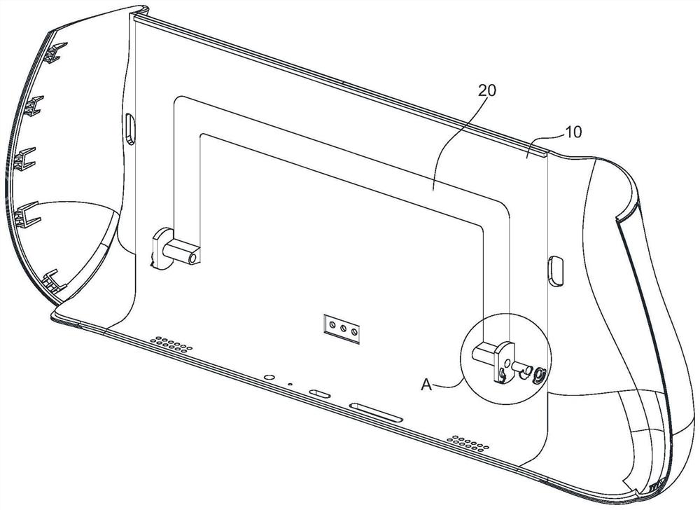
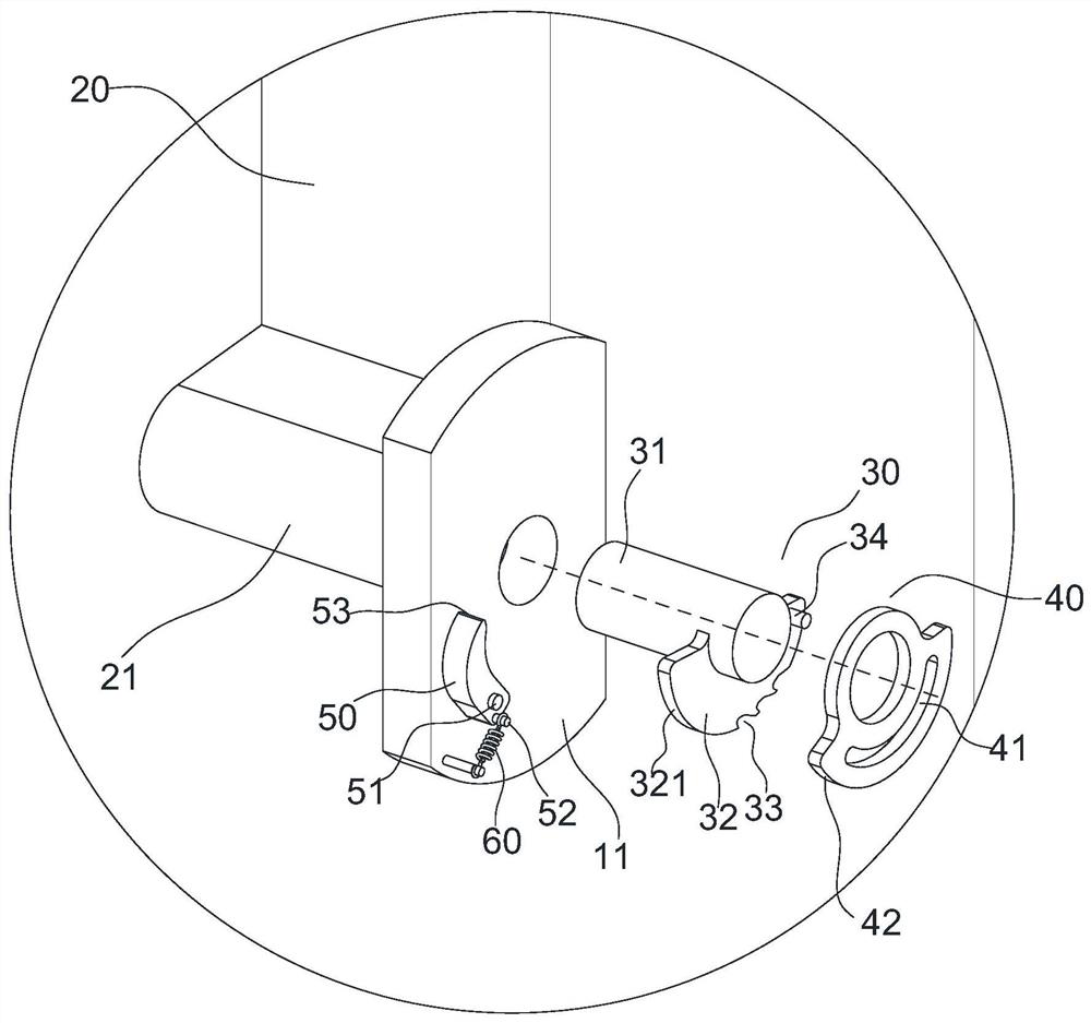
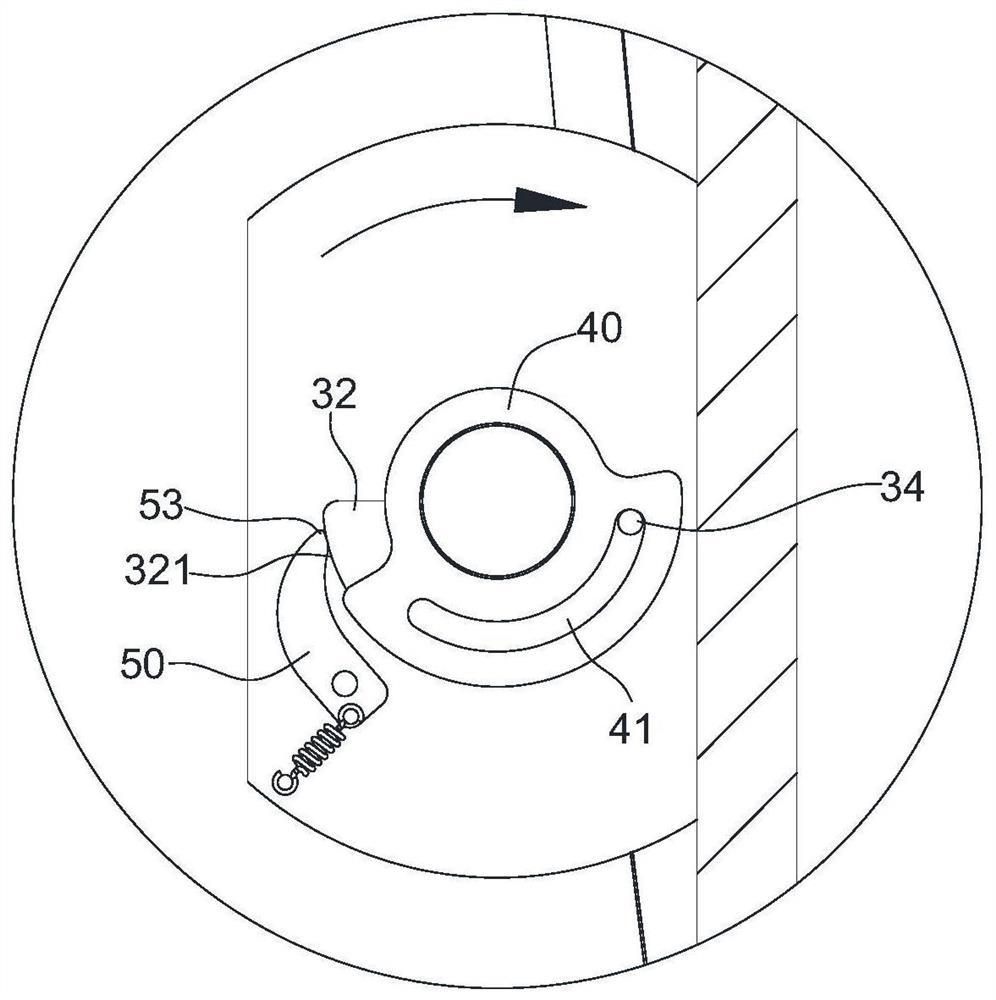
The invention discloses a turnover mechanism and electronic equipment. The turnover mechanism comprises a shell, a support, a rotating disc, a movable disc, a limiting piece and an elastic element, wherein the support is pivotally matched with the shell through a pivot; the rotating disc is fixedly connected to the pivot, the outer periphery face of the rotating disc comprises a first part and a second part, the first part forms a matching face, and the second part is provided with at least two ratchet grooves which are arranged in sequence; a limiting end is arranged on the limiting piece, and the elastic element is installed between the limiting piece and the shell; the movable disc is rotatably arranged on the pivot in a sleeving mode, a sliding groove is formed in the movable disc, thesliding groove comprises a first end and a second end, a pushing part is arranged on the outer periphery of the movable disc, and the distance between the pushing part and the pivot is greater than or equal to the distance between the outer periphery face of the rotating disc and the pivot; and a convex column embedded into the sliding groove is arranged on the rotating disc. According to the turnover mechanism, the support and the shell can be located at multiple different angles, and the service life is long.

Description

technical field [0001] The invention relates to the field of electronic technology, in particular to a turning mechanism and electronic equipment. Background technique [0002] With the continuous development of Internet technology and the continuous popularization of smart terminals, more and more people choose to watch movies, games, and make video calls through mobile phones and other electronic devices. The supporting structure is used to support the electronic equipment, so that the electronic equipment can be prevented from being placed on the desktop at a certain angle, so as to free hands. [0003] The current support structure is usually to set a rotatable bracket on the electronic equipment, and use the external shape of the bracket to limit the maximum rotation angle of the bracket. This kind of support structure can only support the electronic equipment at a fixed angle, and cannot Changing the angle as needed is not convenient enough to use. There are also dam...

Claims


Application Information

Patent Timeline
Patent Type & Authority Applications(China)
IPC IPC(8): F16M11/04F16M11/10
CPCF16M11/04F16M11/10
Inventor 王鹏甘育文
Owner WINGTECH COMM
Why Eureka
Try Eureka