Roller, high-precision bearing and high-end equipment
A technology of rolling bearings and rollers, which is applied in the field of high-end equipment, can solve the problems such as the debris is not easy to be cleaned out, the work of separating the debris is lagging behind, and the maintenance process is complicated, etc. It achieves the effect of easy maintenance, reduced grinding degree, and wide application environment
- Summary
- Abstract
- Description
- Claims
- Application Information
AI Technical Summary
Problems solved by technology
Method used
Image

Examples
Embodiment 1
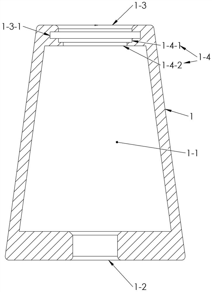
[0048] like figure 1 As shown, the roller housing structure (1) is different from the prior art in that it is used as a constituent part of the bearing roller; it has a main cavity (1-1), a second hole (1-2), a first Three holes (1-3), stepped holes (1-4) and spring holes (1-3-1);
[0049] The stepped hole (1-4) includes a first stepped hole (1-4-1) and a second stepped hole (1-4-2);
[0050] The first end of the main cavity (1-4) passes through the second stepped hole (1-4-2), the first stepped hole (1-4-1) and the circlip hole (1-3-1) in sequence ), the third hole (1-3) communicates with the outside world, and the second end of the main cavity (1-4) communicates with the outside world through the second hole (1-2);
[0051] The second hole (1-2), the third hole (1-3), the first stepped hole (1-4-1), the second stepped hole (1-4-2), the circlip hole (1-4-1) 3-1), the five are round holes, and the five are coaxial;
[0052] The hole diameter of the circlip hole (1-3-1) is la...
Embodiment 2
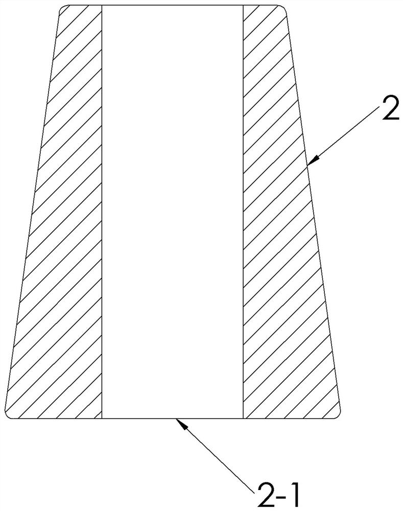
[0063] like figure 2 As shown, the porous element (2) is different from the prior art in that it is designed to fit the roller shell structure (1) described in Embodiment 1, and the porous element (2) has a liquid flow hole ( 2-1).
[0064] Example 2.1. On the basis of Example 2, there is a further optional solution: the material of the porous element (2) is porous sponge.
[0065] Example 2.2 On the basis of Example 2, there is a further optional solution: the structure of the porous element (2) is a single device.
[0066] Example 2.3 On the basis of Example 2, there is a further optional solution: the material of the porous element (2) is a porous thread ball.
[0067] Example 2.4, on the basis of Example 2, a further optional solution: the material of the porous element (2) is filter cotton processed by silk threads.
[0068] Example 2.4, on the basis of Example 2, a further option: the outer three-dimensional geometry of the porous element (2) is adapted to the main c...
Embodiment 3
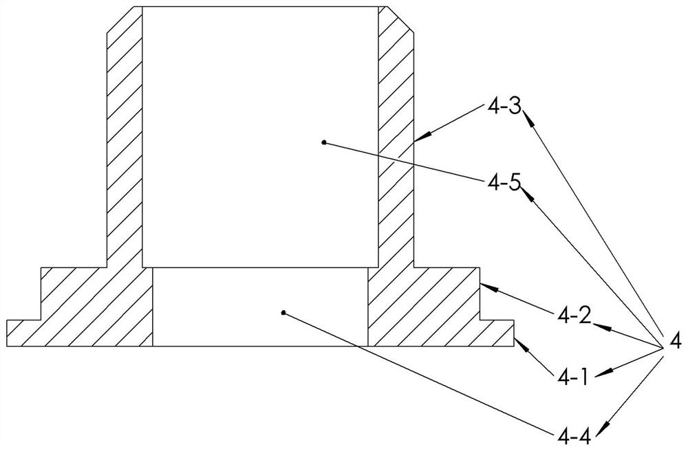
[0070] like image 3 As shown, the hollow column (3), which is different from the prior art, is designed to fit the roller shell structure described in Embodiment 1, and includes a first hollow column segment (3-1), a second hollow column Section (3-2), third hollow column section (3-3); first hollow column section (3-1), second hollow column section (3-2), third hollow column section (3-3) , the three are coaxial; the outer diameter of the second hollow column segment (3-2) is larger than the outer diameter of the third hollow column segment (3-3);
[0071] The third hollow column segment (3-3) has an inner end and an outer end;
[0072] The first hollow column segment (3-1) has an inner end and an outer end;
[0073] The second hollow column segment (3-2) has a first end and a second end;
[0074] The first end of the second hollow column segment (3-2) is connected to the inner end of the first hollow column segment (3-1); the second end of the second hollow column segmen...
PUM
 Abstract
Description
Claims
Application Information
 - Generate Ideas
- Intellectual Property
- Life Sciences
- Materials
- Tech Scout
- Unparalleled Data Quality
- Higher Quality Content
- 60% Fewer Hallucinations
Browse by: Latest US Patents, China's latest patents, Technical Efficacy Thesaurus, Application Domain, Technology Topic, Popular Technical Reports.
© 2025 PatSnap. All rights reserved.Legal|Privacy policy|Modern Slavery Act Transparency Statement|Sitemap|About US| Contact US: help@patsnap.com