Wind driven generator blade root area surface flow control mechanism

A technology of wind power generator and flow control, which is applied to wind power generators, wind power generators consistent with the wind direction, motors, etc. It can solve the problems of water or dust entering the fan blades, affecting the service life, increasing the self-weight of the blades, etc., to prevent water ingress or Dust, increase the service life, ensure the effect of stability

Pending Publication Date: 2022-07-15
INNER MONGOLIA UNIV OF TECH
View PDF1 Cites 0 Cited by
  • Summary
  • Abstract
  • Description
  • Claims
  • Application Information

AI Technical Summary

Problems solved by technology

[0004] In the above-mentioned patent documents, there will be relatively severe vibration when the blade is working, and the working environment is windy, sunny, rainy, winter and summer alternately, and the weld seam is easy to crack, which will cause the seal to fail, causing water or dust to enter the inside of the fan blade , causing the blade to increase its own weight when the blade is working, and affect the service life, and the reed has the risk of falling

Method used


Image

  • Wind driven generator blade root area surface flow control mechanism
  • Wind driven generator blade root area surface flow control mechanism
  • Wind driven generator blade root area surface flow control mechanism

Examples


Embodiment Construction

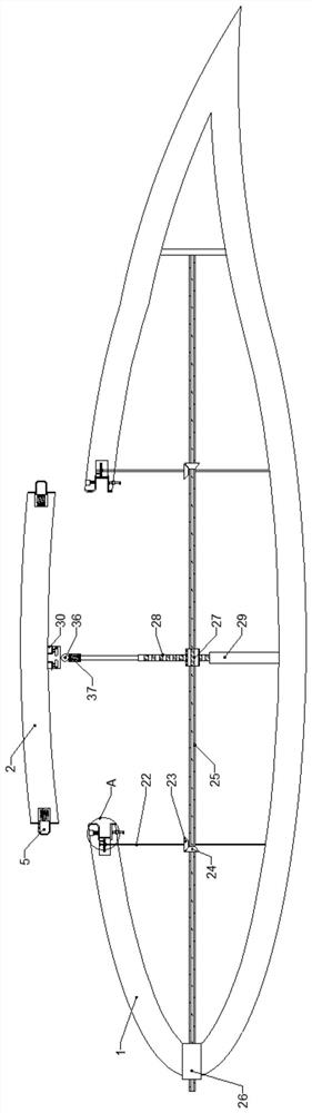
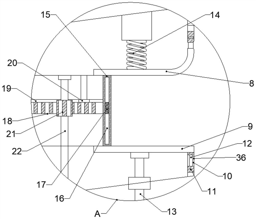
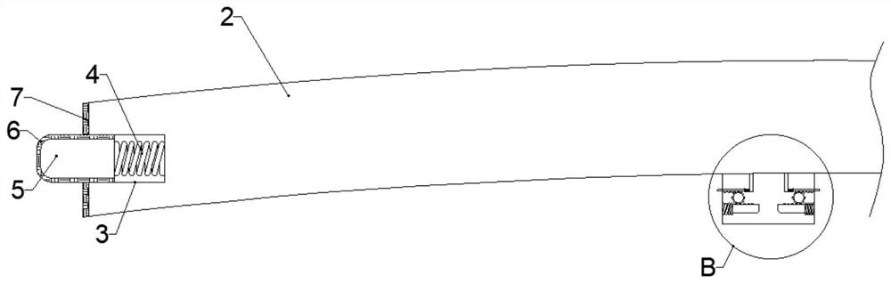
[0021] In this embodiment, a surface flow control mechanism in the root region of a wind turbine blade is as follows: Figure 1-2As shown, it includes a blade 1, a self-vibrating reed 2, a clamping part, a first sealing plate 8, a second sealing plate 9 and a card box 30. The outer surface of the blade 1 is provided with a matching installation for the self-vibrating reed 2 groove, the self-vibrating reed 2 is installed inside the installation groove, the inner wall of the blade 1 close to the end face of the installation groove is installed with a third sealing plate 36, the third sealing plate 36 is perpendicular to the inner wall of the blade 1, and the number of the third sealing plate 36 is Two, two third sealing plates 36 are installed opposite to each other, a sealing groove 10 is opened inside the third sealing plate 36, a sliding plate 12 is slidably connected inside the sealing groove 10, and one end of the sliding plate 12 located inside the sealing groove 10 is conn...


PUM


Abstract

The invention discloses a wind driven generator blade root area surface flow control mechanism which comprises a blade, a self-vibration reed, a clamping component, a first sealing plate, a second sealing plate and a clamping box, the outer surface of the blade is provided with a mounting groove matched with the self-vibration reed, the self-vibration reed is mounted in the mounting groove, and the clamping box is arranged in the mounting groove. Two third sealing plates are mounted on the end face, close to the mounting groove, of the inner wall of the blade, the third sealing plates are perpendicular to the inner wall of the blade, the two third sealing plates are oppositely mounted, a sealing groove is formed in each third sealing plate, and a sliding plate is slidably connected to the interior of each sealing groove; the clamping block can be clamped to the gap between the first sealing plate and the second sealing plate for sealing, the first sealing rubber is arranged on the outer wall of the clamping block so that sealing can be achieved between the clamping block and the first sealing plate and between the clamping block and the second sealing plate, and the effect of preventing water and air from entering is achieved.

Description

technical field [0001] The present invention relates to the technical field of wind power generation. Specifically, it is a surface flow control mechanism in the blade root area of ​​a wind turbine blade. Background technique [0002] At present, wind power generation technology is more and more widely used, and the most important component of wind turbine is the blade; the wind turbine works in the natural environment, under the influence of gust, wind shear, wind direction change and other factors, the blade spanwise airfoil section The inflow angle of attack will fluctuate, resulting in alternating aerodynamic loads on the blades. This alternating load is considered to be the main cause of excessive fatigue and damage to the wind turbine structure; when the amplitude of the angle of attack fluctuation is too large, it will also On the surface of the blade, especially at the blade root, flow separation occurs; large-scale flow separation increases the surface resistance o...

Claims


Application Information

Patent Timeline
Patent Type & Authority Applications(China)
IPC IPC(8): F03D1/06F03D80/00
CPCF03D1/0633F03D1/0675F03D80/00
Inventor 赵爽韩玉霞
Owner INNER MONGOLIA UNIV OF TECH
Why Eureka
Try Eureka