Intelligent driving automobile radar installation device for multiple application scenes
A technology for intelligent driving and automotive radar, applied in measurement devices, vehicle components, and re-radiation, etc., can solve problems such as the impact of radar service life, the adjustment of the angle and height of radar detection, and the impact on the safety of intelligent driving vehicles. Large scope of application, the effect of improving work efficiency
- Summary
- Abstract
- Description
- Claims
- Application Information
AI Technical Summary
Problems solved by technology
Method used
Image
Examples
Embodiment 1
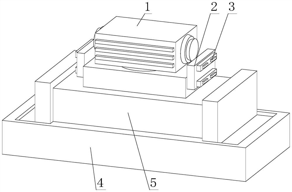
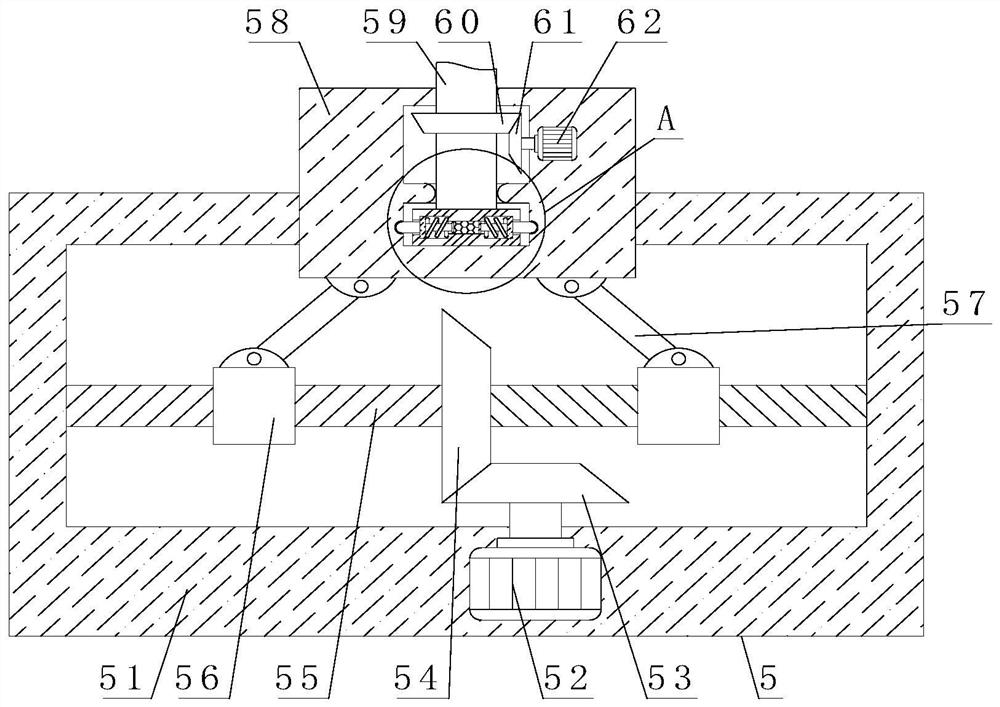
[0039] like Figure 1-5 As shown, the present invention provides an intelligent driving vehicle radar installation device with multiple application scenarios, including a radar 1, an adjustment mechanism 5 is arranged at the bottom of the radar 1, a cooling mechanism 2 is arranged on the side of the adjustment mechanism 5, and the bottom of the adjustment mechanism 5 is arranged An installation mechanism 4 is provided, and an adjustment mechanism 5 includes an adjustment housing 51 . The inner wall of the adjustment housing 51 is movably connected with a threaded post 55 , and the surface of the threaded post 55 is fixedly connected with a No. 2 bevel gear 54 , and a No. 1 motor 52 is arranged inside the adjusting housing 51 . , the output end of the No. 1 motor 52 extends to the inner cavity of the adjustment housing 51 and is fixedly connected with a No. 1 bevel gear 53. The surface of the No. 1 bevel gear 53 meshes with the surface of the No. 2 bevel gear 54. The surface of ...
Embodiment 2
[0042] like Figure 1-5 As shown, on the basis of Embodiment 1, the present invention provides a technical solution: preferably, the installation mechanism 4 includes an installation base 41, the bottom of the inner wall of the installation base 41 is fixedly connected with a slide rail 42, and the surface of the slide rail 42 is slidably connected There is a sliding block 43, the top of the sliding block 43 is fixedly connected with a pressing plate 47, a double-headed motor 46 is arranged inside the mounting base 41, and the output end of the double-headed motor 46 is fixedly connected with a threaded rod 45, and the surface of the threaded rod 45 is threaded An internal thread cylinder 44 is connected, one side of the internal thread cylinder 44 is fixedly connected with one side of the pressing plate 47 , and a protective pad 48 is fixedly connected to the inner cavity of the pressing plate 47 .
[0043] In the present embodiment, the adjusting housing 51 is placed on the ...
Embodiment 3
[0045] like Figure 1-5 As shown, on the basis of Embodiment 1, the present invention provides a technical solution: preferably, the cooling mechanism 2 includes a water tank 22, one side of the water tank 22 is provided with a cooling sheet 3, and a surface of the water tank 22 is fixedly connected with a fixed shell 21 , the other side of the water tank 22 and the inner cavity of the fixed casing 21 is fixedly connected with a fixed pipe 26, the surface of the fixed pipe 26 is provided with a water pump 23, the interior of the fixed casing 21 is provided with a drive motor, and the output end of the drive motor extends to the fixed A movable rod 24 is fixedly connected to the inner cavity of the casing 21 , a fan blade 25 is fixedly connected to the surface of the movable rod 24 , and a blowing hole is opened in the interior of the fixed casing 21 .
[0046] In this embodiment, after the water pump 23 is started, the water in the water tank 22 circulates in the fixed pipe 26...
PUM
 Abstract
Description
Claims
Application Information
 - R&D Engineer
- R&D Manager
- IP Professional
- Industry Leading Data Capabilities
- Powerful AI technology
- Patent DNA Extraction
Browse by: Latest US Patents, China's latest patents, Technical Efficacy Thesaurus, Application Domain, Technology Topic, Popular Technical Reports.
© 2024 PatSnap. All rights reserved.Legal|Privacy policy|Modern Slavery Act Transparency Statement|Sitemap|About US| Contact US: help@patsnap.com


