


Quick Research
Generate reliable direction feasibility study reports for your R&D in just a few steps.

Technical Q&A
Discover and master advanced knowledge NOW. Basics, ideas, possibilities, all at once.

Find Solutions
As an expert in R&D theories, this can generate solutions to your technical problems instantly.

Evaluate Feasibility
Analyze your overall solution with one click, know your potential R&D risks in advance.

Monitor Landscape
Get weekly tech updates, stay abreast of the latest tech innovations and key insights.
Micro-particle solid crushing equipment capable of reducing material loss
A technology of tiny particles and crushing equipment, which is applied in the direction of grain processing, etc., can solve the problems of unsatisfactory crushing effect, low efficiency, and inability to diversify feed, so as to avoid accidental slipping, increase stability, and increase the speed of unloading Effect
- Summary
- Abstract
- Description
- Claims
- Application Information
AI Technical Summary
Problems solved by technology
Method used
Image

Examples
Embodiment 1
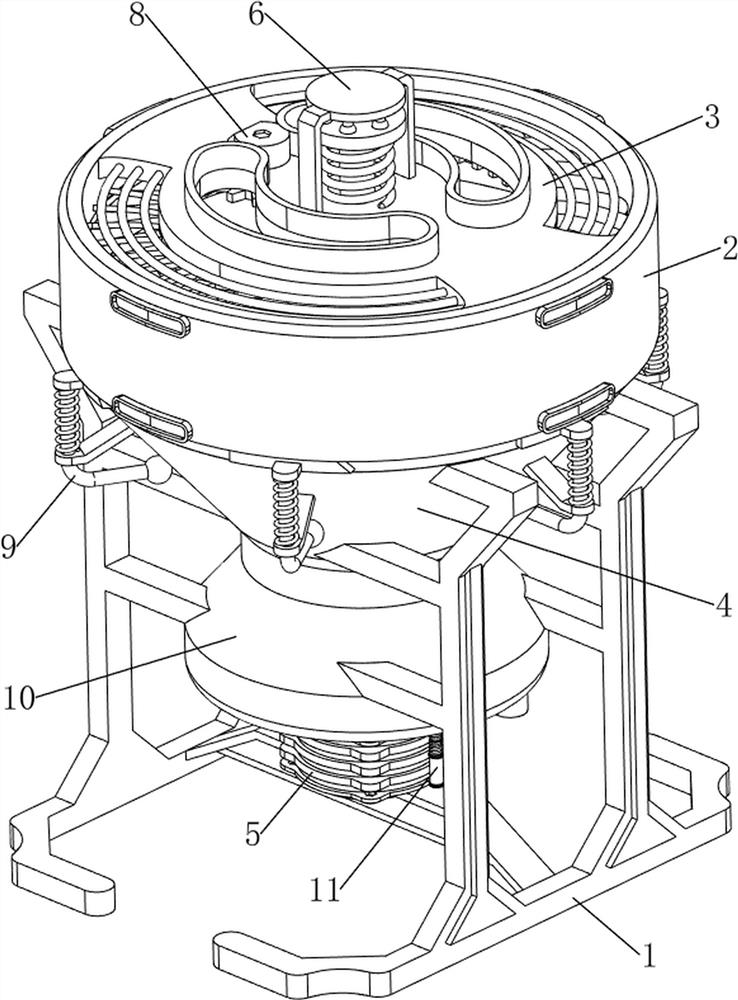
[0035] A small particle solid crushing equipment that reduces material loss, such as figure 1 and image 3 As shown, it includes a first support frame 1, an installation frame 2, a top cover 3, a pulverizing barrel 4, a pulverizing mechanism 5, a pressing mechanism 6 and a scraping mechanism 7, and the left and right sides of the pulverizing barrel 4 are bolted with a first Support frame 1, a mounting frame 2 is welded on the upper side of the crushing barrel 4, a top cover 3 is bolted on the upper inner side of the mounting frame 2, the first support frame 1 is provided with a crushing mechanism 5 for crushing materials, and the top cover 3 is provided with There is a pressing mechanism 6 for crushing materials, and a scraping mechanism 7 for scraping materials is arranged on the crushing mechanism 5 .
[0036] like image 3 , Figure 4 and Figure 11As shown, the crushing mechanism 5 includes a second support frame 12 , a first motor 51 , a prism 52 , a crushing cone 53 ...
Embodiment 2
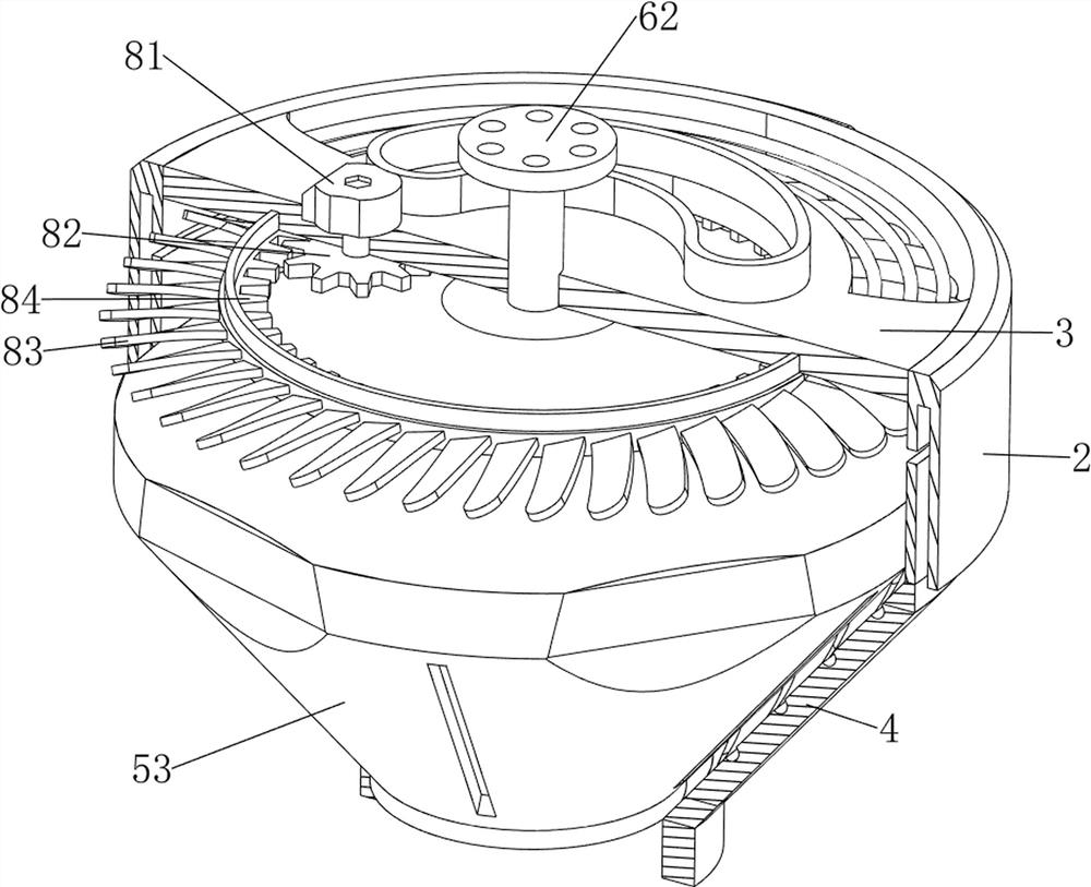
[0041] On the basis of Example 1, as figure 1 and Figure 7 As shown, it also includes a blowing mechanism 8 for convenient feeding. The blowing mechanism 8 includes a second motor 81, a spur gear 82, an annular sector 83 and an inner gear ring 84. The lower side of the top cover 3 is rotatably provided with a The annular fan ring 83 for air circulation, the inner side of the annular fan ring 83 is connected with an inner gear ring 84, and the left part of the top cover 3 is installed with a second power output for power output and the output shaft rotates through the top cover 3 by means of screw connection. The output shaft of the second motor 81 is connected with a spur gear 82 that meshes with the inner gear ring 84 .
[0042] During the cutting operation, the operator starts the second motor 81, the output shaft of the second motor 81 will drive the spur gear 82 to rotate and mesh with the inner gear ring 84, the inner gear ring 84 will drive the annular sector 83 to rot...
Embodiment 3
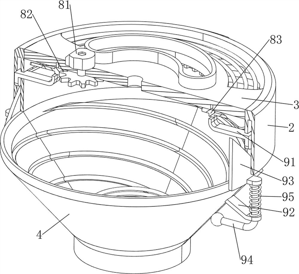
[0044] On the basis of Example 2, as figure 1 , Figure 8 and Figure 9 As shown, it also includes a knocking mechanism 9 for convenient unloading. The knocking mechanism 9 includes a connecting plate 91, a guide plate 92, a wedge plate 93, a knocking rod 94 and a fifth return spring 95. The upper outer side of the crushing barrel 4 Six guide plates 92 are bolted evenly at intervals. The lower part of the guide plates 92 is slidably penetrated by a knocking rod 94 for knocking the pulverizing bucket 4 and in contact with the pulverizing bucket 4. A winding device is connected between the knocking rod 94 and the guide plate 92. The fifth return spring 95 on the outer side of the knock rod 94, the upper part of the knock rod 94 is bolted with a wedge-shaped plate 93 that is slidably matched with the mounting frame 2, and the lower side of the annular sector 83 is evenly welded with six pieces for The connecting plate 91 that squeezes the wedge-shaped plate 93 and is slidably f...
PUM
 Abstract
Description
Claims
Application Information
 - R&D Engineer
- R&D Manager
- IP Professional
- Industry Leading Data Capabilities
- Powerful AI technology
- Patent DNA Extraction
Browse by: Latest US Patents, China's latest patents, Technical Efficacy Thesaurus, Application Domain, Technology Topic, Popular Technical Reports.
© 2024 PatSnap. All rights reserved.Legal|Privacy policy|Modern Slavery Act Transparency Statement|Sitemap|About US| Contact US: help@patsnap.com