
Fireproof power distribution cabinet

A technology for power distribution cabinets and cabinets, which is applied to the substation/power distribution device shell, electrical components, substation/switch layout details, etc., and can solve the problem of low safety factor of power distribution cabinet locks, damage to power distribution cabinet terminal equipment, The electrical cabinet is wet by rain, etc., so as to achieve the effect of simple structure, reducing cleaning times and preventing accidental opening

Inactive Publication Date: 2022-07-12
舒侨雅
View PDF0 Cites 1 Cited by
  • Summary
  • Abstract
  • Description
  • Claims
  • Application Information

AI Technical Summary

Problems solved by technology

[0004] The purpose of the present invention is to provide a fire-proof power distribution cabinet to solve the problem in the above background technology that in the case of heavy rain, poor drainage in the city, and waterlogging, the power distribution Problems such as water ingress inside the electric cabinet can easily cause more serious circuit failures, resulting in damage to the terminal equipment in the power distribution cabinet, causing unimaginable losses and dangers, and the safety factor of the locks installed outdoors is relatively low. Low, it is very easy to cause a false opening state. At the same time, there are many electrical components inside the power distribution cabinet, which will generate a lot of heat when working. Performance and other issues

Method used


Image

  • Fireproof power distribution cabinet
  • Fireproof power distribution cabinet
  • Fireproof power distribution cabinet

Examples

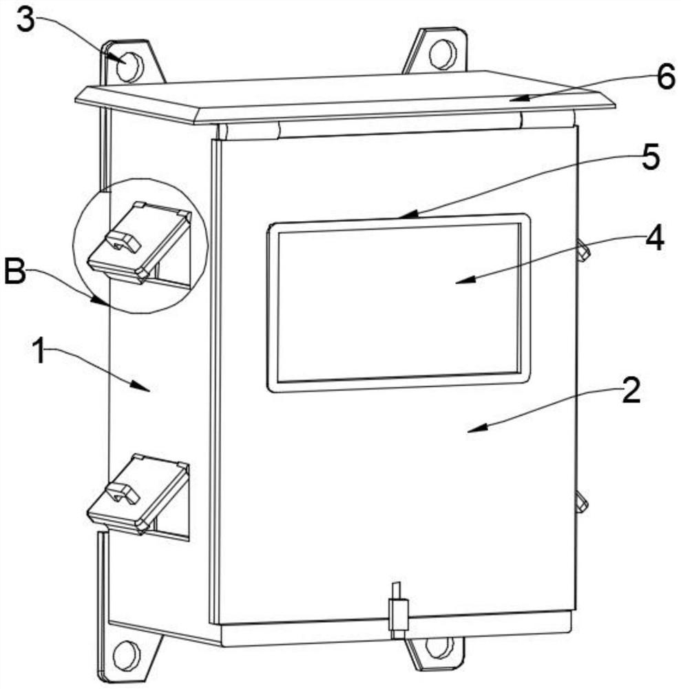
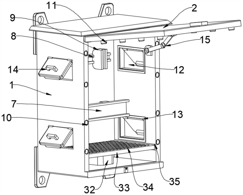
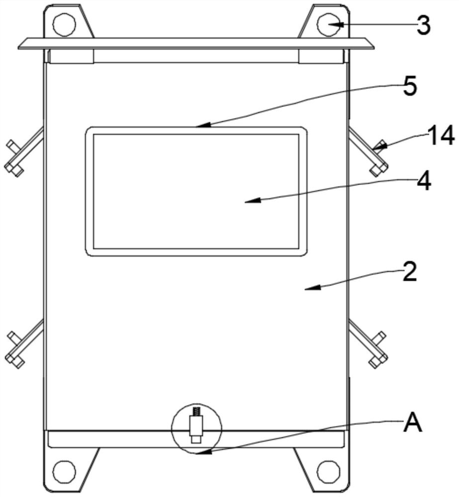

Embodiment Construction

[0025] The technical solutions in the embodiments of the present invention will be clearly and completely described below with reference to the accompanying drawings in the embodiments of the present invention. Obviously, the described embodiments are only a part of the embodiments of the present invention, rather than all the embodiments.

[0026] see Figure 1 to Figure 6 , an embodiment provided by the present invention: a fireproof power distribution cabinet, comprising a cabinet body 1, a cabinet door 2 is installed on the top of the cabinet body 1 through hinges, a bottom surface of the cabinet body 1 is provided with a plug block 20, and the cabinet door The bottom end of the surface is provided with a spring groove 17, a fixed block 16 is provided above the spring groove 17, a slider is installed on the bottom end of the fixed block 16 and is provided in the spring groove 17, and a spring 18 is installed inside the spring groove 17, and the spring 18 One end is fixedly...


PUM


Abstract

The invention discloses a fireproof power distribution cabinet, relates to the technical field of fireproof power distribution cabinets, and solves the problems that the interior of the power distribution cabinet is inconvenient to maintain when the power distribution cabinet is installed, and terminal equipment in the power distribution cabinet is damaged due to the fact that the power distribution cabinet is easily submerged by water. A fireproof power distribution cabinet comprises a cabinet body, a cabinet door is installed at the top end of the cabinet body through hinges, an insertion block is arranged on the surface of the bottom end of the cabinet body, a spring groove is formed in the bottom end of the surface of the cabinet door, a fixing block is arranged above the spring groove, and the top end of the insertion block is arranged in a deep groove in the fixing block. An electric fan is arranged at the bottom end in the cabinet body, and ventilation openings are formed in the two sides of the cabinet body. The inserting blocks are installed in the fixing blocks, the electric fans conduct wind power dust removal on the interior of the cabinet body through the ventilation baffles, the ventilation openings formed in the two ends of the cabinet body have the damp-proof and ventilation effects on the interior of the cabinet body, the overall structure is simple, the cabinet door is more convenient to open, the whole cabinet is clean, and maintenance is more convenient.

Description

technical field [0001] The invention relates to the technical field of fireproof power distribution cabinets, in particular to a fireproof power distribution cabinet. Background technique [0002] With the rapid development of society and economy, power distribution cabinets are divided into power distribution cabinets, lighting distribution cabinets, and metering cabinets, which are the final equipment of the power distribution system. The power distribution cabinet is the general name of the motor control center. In the case of relatively scattered and few circuits, the motor control center is used in the case of concentrated load and many circuits. They distribute the electric energy of a certain circuit of the upper-level power distribution equipment to the nearby load, and this level of equipment should provide protection, Monitoring and Control. [0003] However, in the current situation of heavy rainstorms, poor urban drainage, and waterlogging, the power distributio...

Claims


Application Information

Patent Timeline
Patent Type & Authority Applications(China)
IPC IPC(8): H02B1/28H02B1/56H02B1/32
CPCH02B1/28H02B1/565H02B1/32Y02A30/14
Inventor 舒侨雅
Owner 舒侨雅
Learn More