
Method and system for automatic navigation and positioning cutting of cantilever type heading machine

A cantilever-type roadheader and fully automatic technology, which is applied in navigation, surveying and navigation, earthwork drilling and mining through speed/acceleration measurement, and can solve problems such as inability to accurately locate, inability to follow automatic propulsion, and inability to normalize applications

Pending Publication Date: 2022-07-12
BEIZHING LONGRUAN TEKNOLODZHIS INK
View PDF0 Cites 0 Cited by
  • Summary
  • Abstract
  • Description
  • Claims
  • Application Information

AI Technical Summary

Problems solved by technology

[0004] (1) The cantilever roadheader crawls forward through the crawler belts on both sides, and the encoder cannot accurately measure the mileage and positioning
[0005] (2) The relative coordinate system of the fuselage used in the calculation of the coordinates of the cutting head of the cantilever roadheader cannot accurately grasp the real-time absolute position of the cutting head, and cannot dynamically correct and compensate for the changes in body posture during the working process of the cantilever roadheader. error
[0006] (3) The full-automatic total station is fixedly erected based on the wire point, which requires manual centering of the wire point and fixed installation, and cannot follow the automatic advancement of the tail of the cantilever roadheader
[0007] (4) Based on the distance intersection method of the two backsight control points of the fully automatic total station, due to the narrow and long passage shape of the roadway, the horizontal angle between the two backsight control points and the station of the total station is too small, and the calculation of the rear intersection will be dangerous circle, causing the calculation of geodetic coordinates to fail
[0008] (5) The positioning technology based on point cloud and visual image cannot be applied normally due to the dust and humidity of excavation work

Method used


Image

  • Method and system for automatic navigation and positioning cutting of cantilever type heading machine
  • Method and system for automatic navigation and positioning cutting of cantilever type heading machine
  • Method and system for automatic navigation and positioning cutting of cantilever type heading machine

Examples


Embodiment Construction

[0094] In order to make the above objects, features and advantages of the present invention more clearly understood, the present invention will be described in further detail below with reference to the accompanying drawings and specific embodiments. It should be understood that the specific embodiments described herein are only used to explain the present invention, only a part of the embodiments of the present invention, but not all of the embodiments, and are not used to limit the present invention.

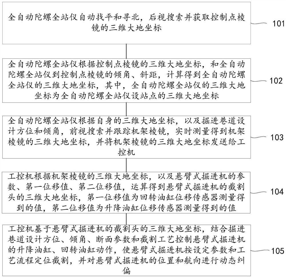
[0095] refer to figure 1 , showing a flow chart of a method for automatic navigation and positioning and cutting of a cantilever roadheader according to an embodiment of the present invention, the method includes:

[0096] Step 101 : the automatic gyro total station automatically leveling and north-seeking, searching backwards and acquiring the three-dimensional geodetic coordinates of the control point prism.

[0097] In the method for automatic navigation and positioning an...


PUM


Abstract

The invention provides an automatic navigation and positioning cutting method and system for a cantilever type heading machine, and relates to the technical field of intelligent mining of coal mines, and the method comprises the following steps: setting the design orientation, inclination angle and section parameters of a heading roadway, automatically leveling and north-seeking a full-automatic gyroscopic total station, searching a roadway traverse point prism in a rearview manner, and calculating the geodetic coordinates of a set site; the geodetic coordinates of a rack prism are searched, tracked and measured in a foresight mode, the geodetic coordinates of a gun head are calculated in real time based on lifting and rotating oil cylinder displacement values and the physical size of the heading machine, and lifting and rotating oil cylinder actions of the heading machine are controlled by combining the heading roadway design orientation, the dip angle, section parameters and the cutting process. The heading machine is enabled to perform positioning cutting according to set parameters and technological processes, and position and heading can be dynamically rectified. The absolute geodetic coordinates of the cutting head and the relative coordinates under the cutting section coordinate system are calculated in real time, unification of the absolute coordinates and the relative coordinates is guaranteed, and errors caused by posture changes of a machine body in the working process of the cantilever type heading machine can be dynamically corrected and compensated.

Description

technical field [0001] The invention relates to the technical field of intelligent mining in coal mines, in particular to a method and system for automatic navigation, positioning and cutting of a cantilever roadheader. Background technique [0002] At present, when the cantilever roadheader is working in the underground roadway, the laser light spot formed on the roadway section surface is mainly used as the basis for navigation and positioning during the roadway operation through the laser pointing instrument arranged by the production mine surveying and mapping technicians based on the roadway wire points. During the excavation operation of the coal mine roadway, the environment of the excavation face is very harsh, with large noise, large dust, high humidity and high temperature, and the work of personnel is dangerous and labor-intensive. Although the traditional laser pointer can also meet the daily production requirements, it depends to a large extent on the experience...

Claims


Application Information

Patent Timeline
IPC IPC(8): G01C21/16G01C21/18G01C25/00G01C15/00E21D9/10
CPCG01C21/16G01C21/18G01C25/005G01C15/00E21D9/108E21D9/003Y02P90/02
Inventor 毛善君李鑫超陈华州宋春久朱义宏
Owner BEIZHING LONGRUAN TEKNOLODZHIS INK
Learn More