Oil-gas long-distance pipeline device with plugging function

A long-distance pipeline, oil and gas technology, applied in the direction of pipe components, pipes/pipe joints/fittings, flange connections, etc., can solve the problems of inconvenient maintenance, easy water corrosion of pipelines, and pipelines that cannot be sealed in time, so as to facilitate maintenance , prevent corrosion damage, and prevent continuous leakage

Pending Publication Date: 2022-07-12
湖北文豆思来科技有限公司
View PDF0 Cites 2 Cited by
  • Summary
  • Abstract
  • Description
  • Claims
  • Application Information

AI Technical Summary

Problems solved by technology

[0007] The purpose of the present invention is to provide a long-distance oil and gas pipeline device with a plugging function, so as to solve the problem that the leakage of the pipeline proposed in the above-mentioned background technology cannot be sealed in time; the lack of a mechanism for sealing a single pipeline makes it inconvenient for maintenance ; At the same time, there are problems related to water ingress and corrosion between the two sets of pipes

Method used


Image

  • Oil-gas long-distance pipeline device with plugging function
  • Oil-gas long-distance pipeline device with plugging function
  • Oil-gas long-distance pipeline device with plugging function

Examples


Embodiment 1

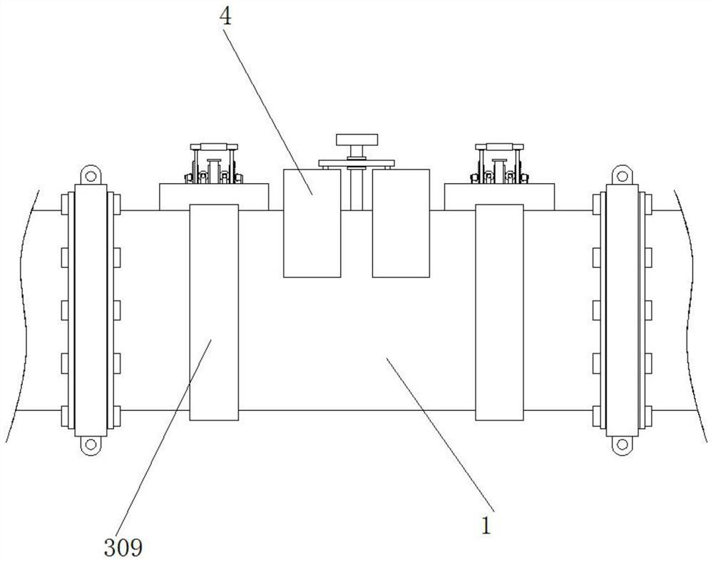
[0042] Example 1, as Figure 7-8 As shown in the figure, there is a leak somewhere in the pipeline. At this time, slide the nearest sliding ring 309 to the leaking place, and rotate the sliding ring 309 to rotate the mounting frame 301 to the top of the leaking place. At this time, pull the handle 308 to drive the telescopic The rod 304 moves upward, the handle 308 drives the first thorn rack 306 to move upward, the teeth on the first thorn rack 306 and the second thorn rack 1303 slide with each other, and the upwardly moving telescopic rod 304 is driven by the first rack 302 The two sets of gears 305 rotate, and the two sets of gears 305 push the second rack 307 toward the leak. At this time, the sealing block 303 is close to the leak and blocks it, which can be temporarily blocked and prevented from leaking. At the same time, the two sets of springs 1302 The second thorn rack 1303 is engaged with the first thorn rack 306 to prevent the handle 308 from moving in the opposite ...

Embodiment 2

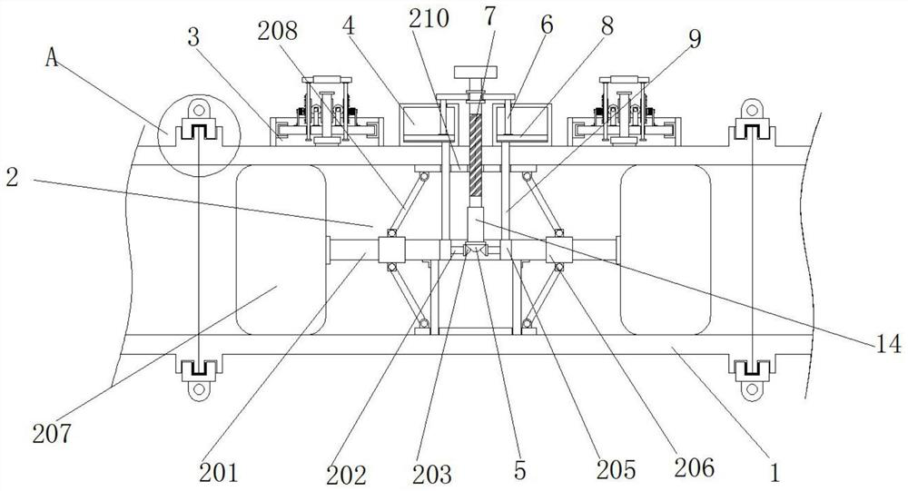
[0043] Example 2, as Figure 1-6 As shown, when a certain section of pipeline needs to be repaired, disassembled and replaced, the second threaded rod 7 is rotated at this time, so that the second threaded rod 7 moves to the inside of the pipeline 1, and the second threaded rod 7 drives the pressing rod 6 and the arc The shaped plate 8 moves downward, so that the arc-shaped plate 8 transports the air inside the air storage chamber 4 through the conduit 9, the connecting chamber 205 and the air intake pipe 204 to the interior of the air bag 207, so that the air bag 207 is expanded, and the pipeline is blocked and blocked. At the same time, the second threaded rod 7 drives the sleeve 14 and the first bevel gear 5 to rotate, and the first bevel gear 5 drives the first threaded rod 202 to rotate through the two sets of second bevel gears 203 , so that the sliding sleeve 206 slides on the outside of the connecting rod 201 , the top plate 210 is pushed to the outside of the pipe 1 t...


PUM


Abstract

The oil and gas long-distance pipeline device with the plugging function comprises a pipeline, the two sides of the outer side of the pipeline are sleeved with leakage-proof assemblies, a supporting assembly is arranged in the middle of the bottom of the interior of the pipeline, and a second threaded rod is arranged in the middle of the top of the pipeline. The bottom of the outer side of the second threaded rod is sleeved with a sleeve, a first bevel gear is arranged at the bottom of the sleeve, and gas storage bins are arranged on the two sides of the top of the pipeline. A sliding ring drives a mounting frame to move to the position above a leakage position, a handle is pulled outwards, through a series of transmission, a second rack drives a sealing block to get close to the sealing position, a notch is blocked through extrusion force, the leakage position can be rapidly and temporarily blocked, continuous leakage of petroleum is prevented, and the service life of the petroleum is prolonged. The loss is reduced.

Description

technical field [0001] The invention relates to the technical field of long-distance oil and gas pipeline devices, in particular to a long-distance oil and gas pipeline device with a plugging function. Background technique [0002] The oil and natural gas industry is the lifeline industry that is related to the survival and development of the country, and the pipeline transportation of oil and gas is the most important mode of transportation in the petrochemical industry. Therefore, ensuring the safe and efficient operation of the oil and gas pipeline system is essential for ensuring the safety and stability of the petrochemical industry and the long-term development of the country. Development is important. [0003] The current long-distance oil and gas pipeline installations have certain shortcomings: [0004] 1. Since the existing pipelines are directly exposed to the outside world, natural disasters such as corrosion, landslides and debris flows, and third-party damage ...

Claims


Application Information

Patent Timeline
Patent Type & Authority Applications(China)
IPC IPC(8): F16L55/12F16L23/024F16L23/16
CPCF16L55/12F16L23/024F16L23/16Y02T10/30
Inventor 干倩文
Owner 湖北文豆思来科技有限公司
Why Eureka
Try Eureka