Clamping mechanism for wind power flange radial drilling

A technology of clamping mechanism and wind power flange, which is applied in wind power generation, boring/drilling, drilling/drilling equipment, etc. Maintain the stability of the accuracy of the opening of the hole position and other issues, to achieve the effect of improving convenience

Active Publication Date: 2022-07-12
JIANGYIN HENGRUN RING FORGING
View PDF9 Cites 1 Cited by
  • Summary
  • Abstract
  • Description
  • Claims
  • Application Information

AI Technical Summary

Problems solved by technology

[0003] Before drilling, the wind power flange needs to be clamped and positioned by the clamping mechanism, so that the wind power flange has high stability when drilling The accuracy of opening the inner diameter of the hole is relatively standard, but the current clamping mechanism is composed of two splints and a bottom carrier plate. There will be a lot of debris on the surface of the wind power flange. When the wind power flange is placed next time, due to the debris, the wind power flange will not be able to fit the surface of the clamping mechanism, which will affect the stability of the clamping and the opening of the hole. Accuracy, and because the surface of the wind power flange will be on the carrier plate, the debris inside the hole of the wind power flange after drilling cannot be left synchronously, which will affect the subsequent use of the wind power flange

Method used


Image

  • Clamping mechanism for wind power flange radial drilling
  • Clamping mechanism for wind power flange radial drilling
  • Clamping mechanism for wind power flange radial drilling

Examples


Embodiment 1

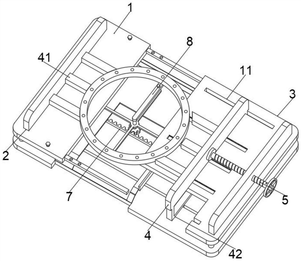
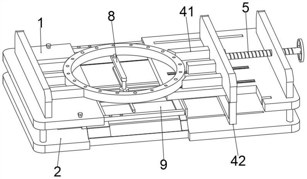
[0037] see Figure 1-Figure 7 As shown, the purpose of this embodiment is to provide a clamping mechanism for radial drilling of wind power flanges, including at least:

[0038] Fixed plate 1, one side of the fixed plate 1 is provided with a positioning plate 3, there is a gap between the fixed plate 1 and the positioning plate 3, and the gap is used to drop the drilling debris of the wind power flange. A mounting plate 2 is installed on the surface, a positioning block 4 is arranged on the surface of the positioning plate 3, and a positioning column 41 is installed on the side of the positioning block 4 and one of the mounting plates 2, and the positioning column 41 is used for clamping the wind power flange. Fixed, a screw 5 is provided between the positioning block 4 and one of the mounting plates 2, the screw 5 is threadedly connected to the mounting plate 2, and the screw 5 is used to push and offset the position of the positioning block 4;

[0039] Support plate 6, the ...

Embodiment 2

[0049] Considering that the positioning column 41 only clamps and fixes the side of the wind power flange, after the wind power flange contacts the drilling equipment, the drilling equipment itself has a large vibration, which will cause the overall wind power flange to shake. This embodiment makes further improvements on the basis of Embodiment 1, such as Figure 8 and Figure 9 shown:

[0050] The surface of the positioning column 41 is provided with a shifting slot 413, the shifting slot 413 extends out of the surface of the positioning column 41, and the inner side of the shifting slot 413 is slidably connected with a pressure block 414, and the pressure block 414 is used for contacting the top side of the wind power flange. After the positioning post 41 is attached to the wind power flange, the pressing block 414 slides along the inner side of the shifting groove 413 to the outside. When the pressure block 414 sticks out to fit the wind power flange, the end position of...

Embodiment 3

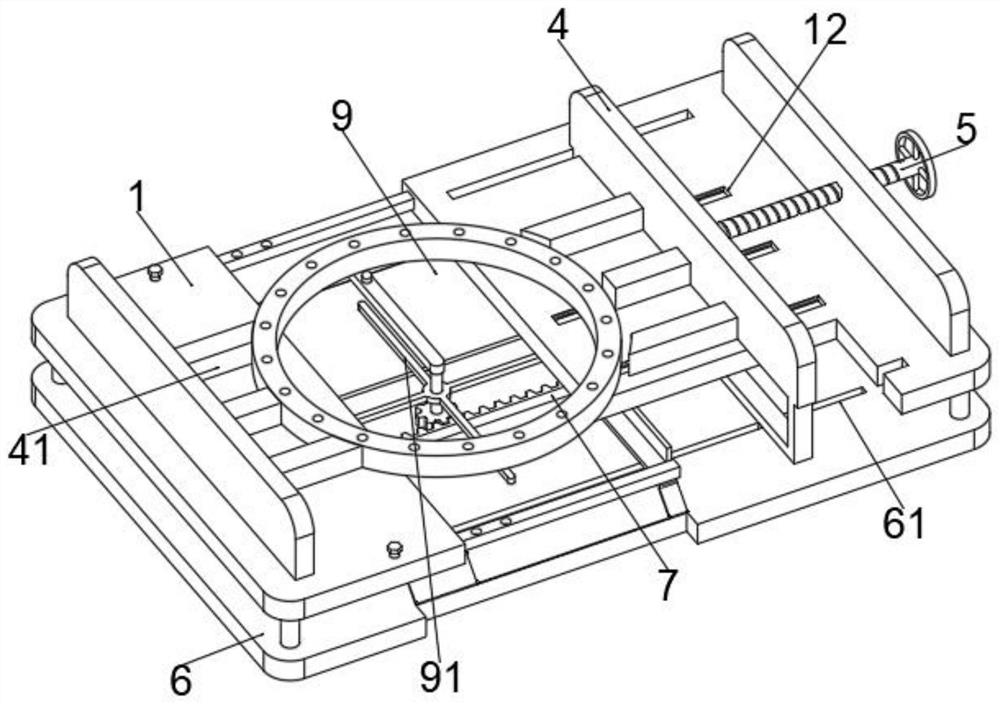
[0052] Considering that the gap between the fixed plate 1 and the positioning plate 3 is limited, the rotation of the ring sticking plate 8 will be restricted by the sides of the fixed plate 1 and the positioning plate 3. This embodiment makes further improvements on the basis of the second embodiment, such as Figure 10 shown:

[0053] The surfaces of the fixing plate 1 and the positioning plate 3 are provided with a cavity 13, the cavity 13 is located directly below the wind power flange, and the cavity 13 is used to discharge the debris in the hole of the wind power flange, which is located on the fixed plate through the wind power flange. 1 and the positioning plate 3, and after opening the holes, the partial holes of the wind power flange will be located on the cavity 13, so that the local debris in the holes of the wind power flange will fall down through the cavity 13, When the wind power flange is rotated through the ring plate 8, a small part of the debris in the wind...


PUM


Abstract

The invention relates to the technical field of wind power flange machining, in particular to a clamping mechanism for wind power flange radial drilling. The supporting plate at least comprises a fixing plate, a positioning plate is arranged on one side of the fixing plate, mounting plates are mounted on the surfaces of the fixing plate and the positioning plate, a positioning block is arranged on the surface of the positioning plate, a screw is arranged between the positioning block and one mounting plate, the driven part at least comprises a driven wheel, and the driven wheel rotates on the surface of the supporting plate. The side face of the driven wheel is connected with a rack in a meshed mode, the rack is fixedly connected with the driving arm, an annular pasting plate is arranged above the driven wheel, and the bottom face of the protrusion is elastically connected with the annular pasting plate through a spring. The wind power flange is driven to rotate through rotation of the annular flitch plate, a local drill hole of the wind power flange deviates from the current position, chippings in the drill hole fall into the gap, and chippings of the fixing plate and the positioning plate fall into the gap in a statistical mode through rotation and friction of the wind power flange.

Description

technical field [0001] The invention relates to the technical field of wind power flanges, in particular to a clamping mechanism used for radial drilling of wind power flanges. Background technique [0002] Wind power flange is a large flange used for the inner side of large industrial equipment or machinery. When the wind power flange is produced, the surface of the wind power flange needs to be drilled with radial drilling equipment to make holes. Conducive to the subsequent use of wind power flanges. [0003] Before the drilling operation, the wind power flange needs to be clamped and positioned by the clamping mechanism, so that the wind power flange has high stability when drilling, and the accuracy of opening the inner diameter of the hole is relatively standard. The clamping mechanism is composed of two clamping plates and a bottom carrier plate. After clamping, after the drilling equipment opens the wind power flange hole position, a large amount of wind power flang...

Claims


Application Information

Patent Timeline
IPC IPC(8): B23Q3/06B23B41/00B23B47/00B23Q11/00
CPCB23Q3/062B23B41/00B23B47/00B23Q11/0042B23Q11/0053B23Q2703/10B23Q2703/12B23B2270/30B23B2270/28Y02E10/72
Inventor 承天洋沈忠协孙峰唐广林周敏承刚
Owner JIANGYIN HENGRUN RING FORGING
Why Eureka
Try Eureka