
Load holding valve

A valve block and hydraulic valve technology, applied in the field of hydraulic valves, can solve the problems of loss of operating fluid, structural defects, loose sealing elements, etc., and achieve the effect of cheap and simple structure

Pending Publication Date: 2022-07-08
ATLANTIC FLUID TECH
View PDF1 Cites 0 Cited by
  • Summary
  • Abstract
  • Description
  • Claims
  • Application Information

AI Technical Summary

Problems solved by technology

Such an overpressure, especially if it is repeated over time, can even lead to structural defects in the valve, such as for example loosening of the closing element of the opening arranged outside the valve block
[0007] Additional disadvantages of prior art valves include the risk of loss of operating fluid and leakage

Method used


Image

  • Load holding valve
  • Load holding valve
  • Load holding valve

Examples


Embodiment Construction

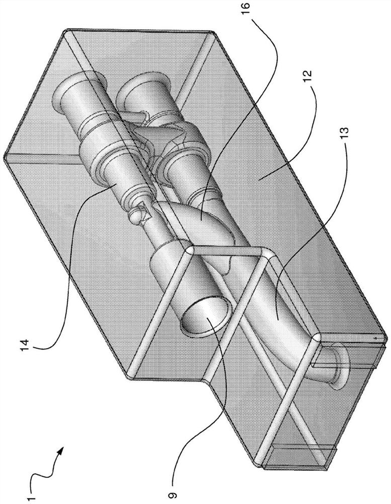
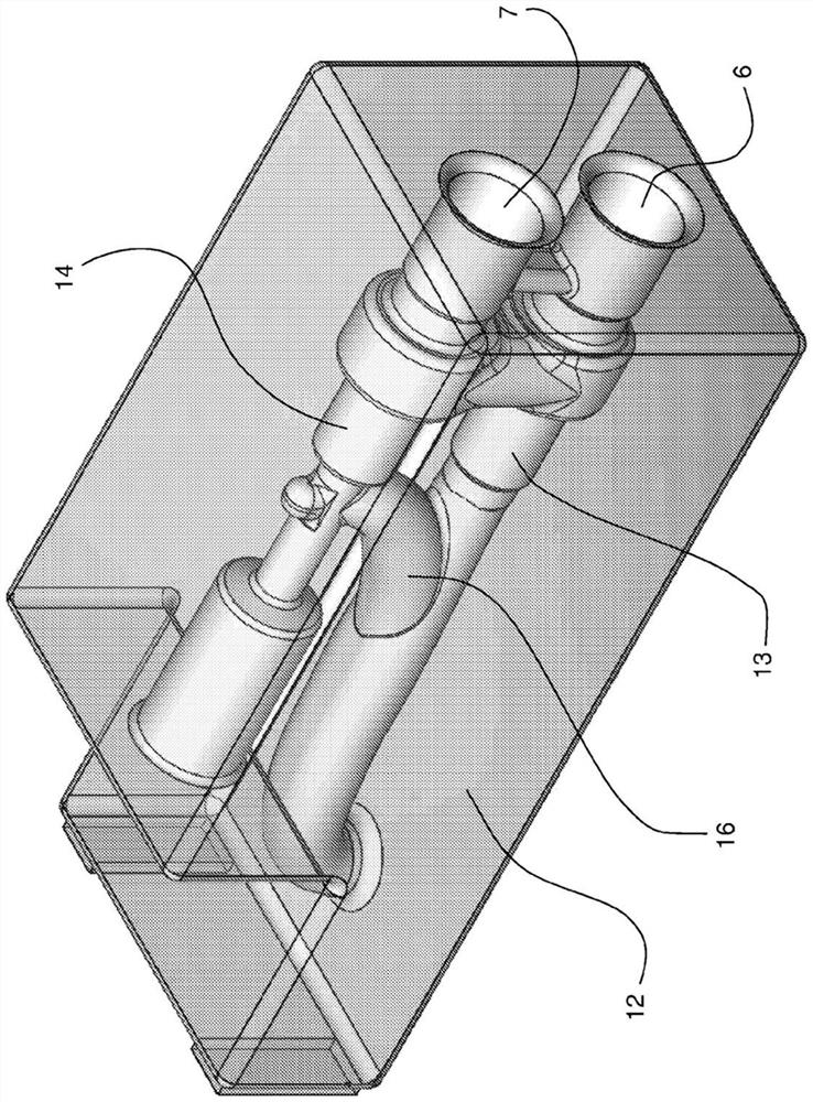
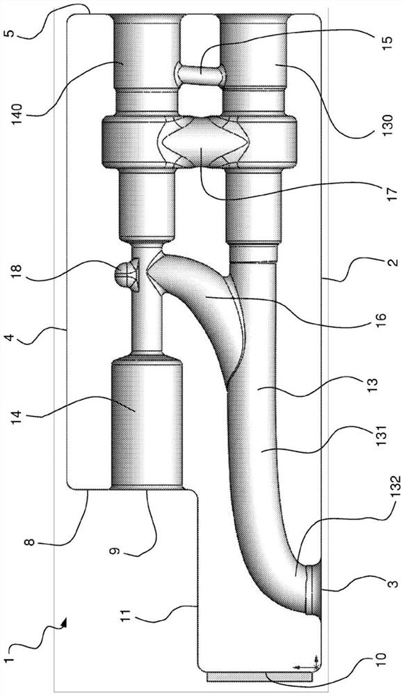
[0031] Referring to the preceding figures, the valve block of the hydraulic valve is generally designated with 1 . Hydraulic valves may include, in particular, hydraulic valves, which may be used, for example, in earthmoving machines such as in excavators.

[0032] The valve block 1 can in particular be produced in one piece, for example by moulding molten material in a moulding cavity. In particular, the valve block 1 can be produced by melting and casting metal in a mould. The metal may include, among other things, cast iron or another material that can be used in the casting process.

[0033] The valve block 1 may in particular comprise cavity means obtained in the valve block 1 in order to define conduits and openings for conveying pressurized fluid (liquid, especially oil).

[0034] The valve block 1 can in particular comprise at least one first side 2 with at least one first opening 3 . The first opening 3 can in particular be provided in fluid connection with a hydra...


PUM


Abstract

The invention relates to a hydraulic valve for an excavator, which can limit the loss of hydraulic loads and the deformation of the valve due to overpressure, comprising a one-piece valve block (1), in which a first line (13) connects two openings (3, 6), one of which is arranged on a side (5) of the valve block, and a second line (14) connects the other two openings (7, 9), wherein one opening (7) is arranged on said side (5), and the other two ducts (15, 16) connecting the first duct (13) to the second duct (14), in which the connecting duct (15) is close to said side (5) and the other connecting duct (16) is away from said side (5) and extends with an inclined longitudinal axis so as to advance from the first duct (13) to the second duct (14) close to said side (5).

Description

technical field [0001] The present invention relates to a hydraulic valve through which a pressurized fluid is passed, in particular a hydraulic valve configured to operate at relatively high fluid flow rates (eg, up to a value of the order of hundreds of liters / minute) and relatively high pressures (eg, up to 420bar fluid pressure) hydraulic valve. Background technique [0002] Specifically, but not exclusively, the valve in question can be applied to earthmoving machines, especially in order to support even very large suspended loads, such as, for example, the articulated arms of excavators, and to keep said suspended loads in a desired position A set time interval, sometimes hours. The valve in question is supplied with pressurized fluid and through the valve, the pressurized fluid is sent to an actuator, usually a double-acting hydraulic cylinder, which in turn is connected to the load to be supported. [0003] In particular, it refers to a valve according to the pream...

Claims


Application Information

Patent Timeline
IPC IPC(8): F16K27/02
CPCF16K27/0209F15B13/0814F15B13/0871F15D1/04
Inventor C·斯托尔奇
Owner ATLANTIC FLUID TECH
Learn More