
MEMS gyroscope

A gyroscope and anchor point technology applied to MEMS gyroscopes. It can solve the problems of three-axis detection MEMS gyroscope detection modal coupling, error superposition, etc., and achieve the effect of favoring bias stability, reducing displacement, and reducing quadrature error.

Pending Publication Date: 2022-07-08
瑞声开泰科技(武汉)有限公司 +1
View PDF2 Cites 0 Cited by
  • Summary
  • Abstract
  • Description
  • Claims
  • Application Information

AI Technical Summary

Problems solved by technology

[0005] The purpose of the present invention is to provide a MEMS gyroscope to solve the problem of error superposition caused by three-axis detection MEMS gyroscope detection mode coupling in the prior art

Method used


Image

  • MEMS gyroscope
  • MEMS gyroscope
  • MEMS gyroscope

Examples


Embodiment Construction

[0037] The present invention will be further described below with reference to the accompanying drawings and embodiments.

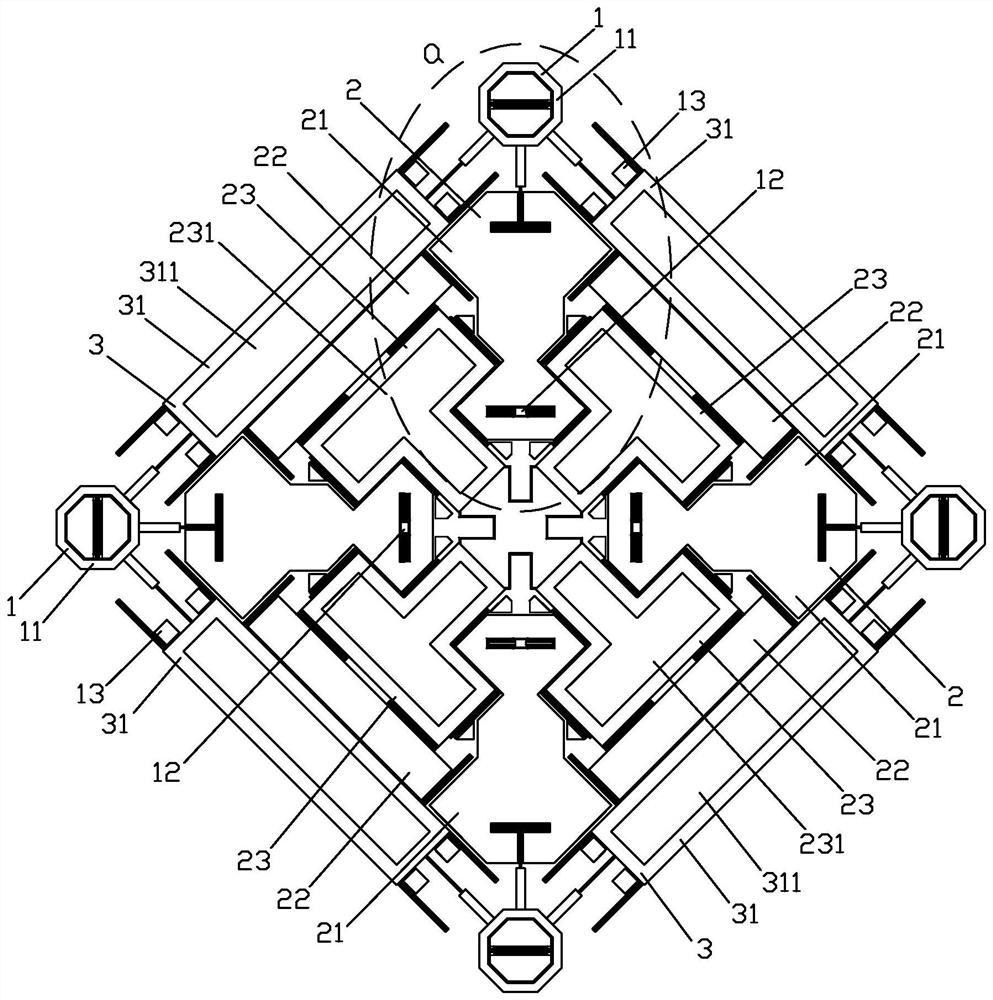
[0038] like figure 1 As shown in , a MEMS gyroscope provided in the embodiment of the present invention includes an anchor point unit 1, a sensing unit 2 elastically connected to the anchor point unit 1, and a driving unit elastically connected to the anchor point unit 1 and the sensing unit 2 3;

[0039] The anchor point unit 1 includes four corner anchor point structures 11 respectively located at four corner positions of a rectangle and four center anchor points 12 located in the rectangle and spaced from the four corner anchor point structures 11 respectively;

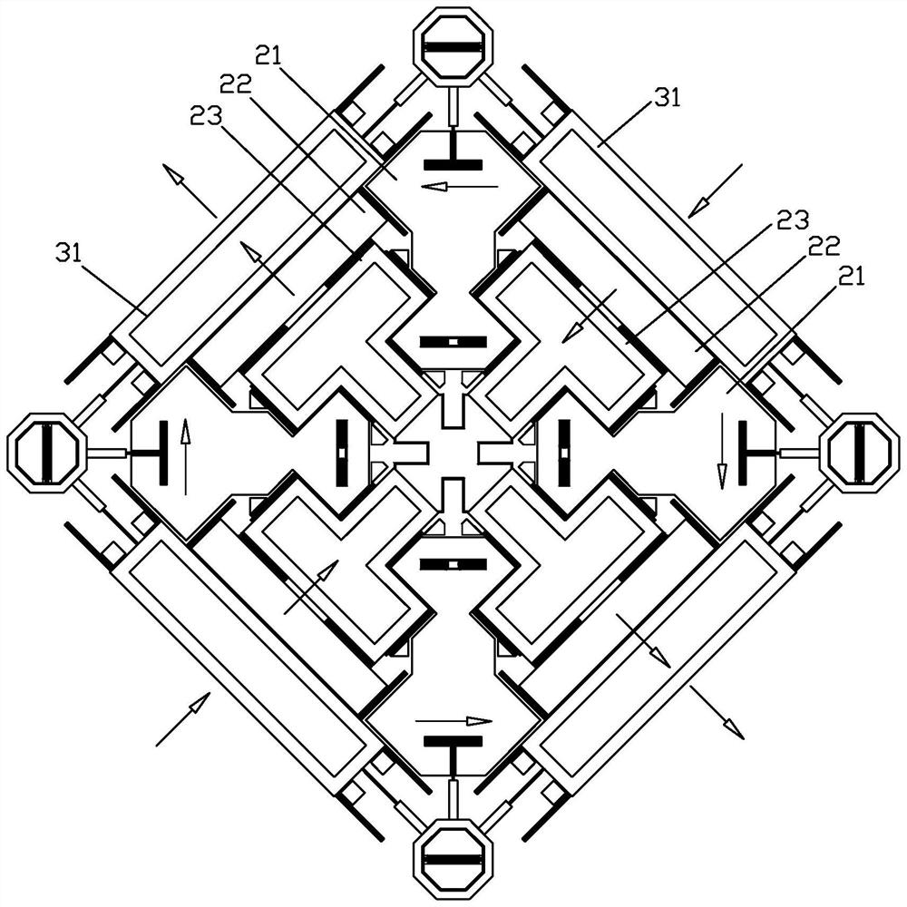
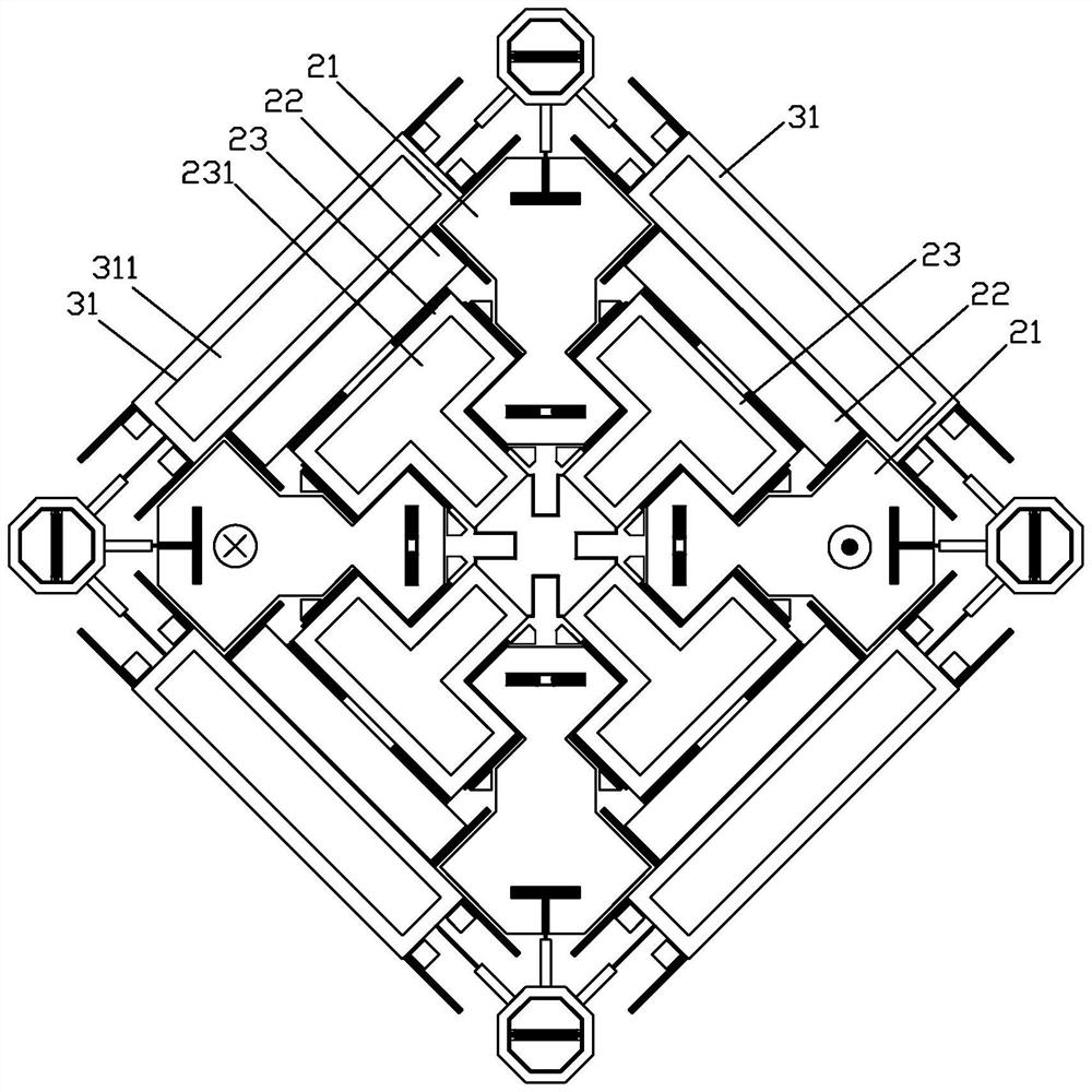
[0040] The sensing unit 2 includes four first mass blocks 21 that are elastically connected between each corner anchor point structure 11 and the corresponding central anchor point 12 and form a space for each other, and four mass blocks 21 that are respectively located in each space. The se...


PUM


Abstract

The invention provides an MEMS gyroscope. The MEMS gyroscope comprises an anchor point unit, a sensing unit elastically connected to the anchor point unit, and a driving unit elastically connected to the anchor point unit and the sensing unit, the anchor point unit comprises four corner anchor point structures located at the four corner positions of a rectangle and four center anchor points. The sensing unit comprises four first mass blocks, four second mass blocks and four decoupling mass blocks, wherein the four first mass blocks are elastically connected between the corner anchor point structures and the corresponding center anchor points respectively and form receding spaces mutually, and the four second mass blocks and the four decoupling mass blocks are located in the receding spaces respectively; the first mass block, the second mass block and the decoupling mass block are all arranged in a rectangle; the driving unit comprises four driving pieces connected to the outer side of the second mass block. According to the gyroscope, independent detection of angular velocities of three axes can be realized, differential detection can be realized, the vibration moment is balanced, the influence of acceleration impact and orthogonal error is effectively resisted, and the detection precision is improved.

Description

【Technical field】 [0001] The invention relates to the technical field of gyroscopes, in particular to a MEMS gyroscope. 【Background technique】 [0002] Micro-mechanical gyroscope, namely MEMS (Micro Electro Mechanical systems) gyroscope, is a typical angular velocity micro-sensor, which has a very wide range of applications in the consumer electronics market due to its advantages of small size, low power consumption and convenient processing. In recent years, with the gradual improvement of the performance of MEMS gyroscopes, MEMS gyroscopes are widely used in automotive, industrial, virtual reality and other fields. [0003] US Patent US8459110B2 (Chinese family CN102183246B) discloses an integrated MEMS gyroscope, comprising a first driving mass and a second driving mass, and the first driving mass and the second driving mass respond to the angular velocity felt by the gyroscope to generate The motion is sensed, and then the angular velocity is measured by detecting the s...

Claims


Application Information

Patent Timeline
Patent Type & Authority Applications(China)
IPC IPC(8): G01C19/5656
CPCG01C19/5656G01C19/5747G01C19/5733G01C19/5769B81B2201/0242
Inventor 马昭占瞻阚枭杨珊严世涛彭宏韬李杨黎家健陈秋玉
Owner 瑞声开泰科技(武汉)有限公司
Learn More