
Turbine guide blade welding positioning method

A turbine guide vane, welding positioning technology, applied in welding equipment, auxiliary welding equipment, welding/cutting auxiliary equipment, etc., can solve the problem of large error of turbine blades

Pending Publication Date: 2022-07-08
AECC SHENYANG ENGINE RES INST
View PDF0 Cites 0 Cited by
  • Summary
  • Abstract
  • Description
  • Claims
  • Application Information

AI Technical Summary

Problems solved by technology

[0007] The purpose of this application is to provide a turbine guide vane welding positioning method to solve the problem of large errors in the positioning of turbine blades by using the six-point positioning method in the prior art

Method used


Image

  • Turbine guide blade welding positioning method
  • Turbine guide blade welding positioning method
  • Turbine guide blade welding positioning method

Examples


specific Embodiment approach

[0058] As a specific implementation manner, a group of high-pressure turbine guide vanes that are welded by a certain two vanes are selected for description below, and the positioning before welding is performed according to the following method.

[0059] 1. Calculate the theoretical value

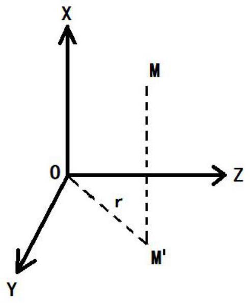
[0060] The Cartesian coordinate system that defines the theoretical blade is (X, Y, Z), the X axis is the engine axis, and the Z axis is the radial direction of the blade. The radius r of the cylindrical tangent surface is the distance from the origin O to the projected point M' of the point M on the plane YOZ, r∈[0,∞).

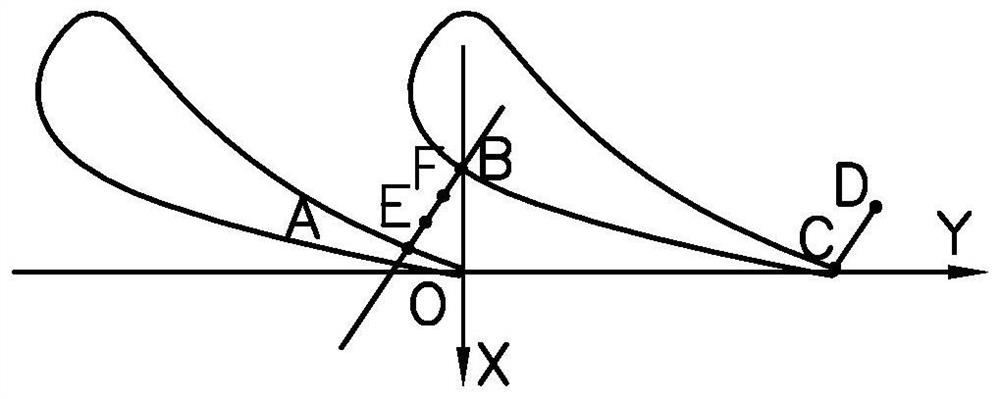
[0061] According to the blade profile distribution in the radial direction, three groups of r values ​​are determined, which are numbered from 1 to 3 from the blade tip to the blade root, and r 1 =340mm, r 2 =330mm, r 3 =320mm.

[0062] respectively use r 1 , r 2 , r 3 The blade is cut from the cylindrical section at the maximum value, and three sets of intersectio...


PUM


Abstract

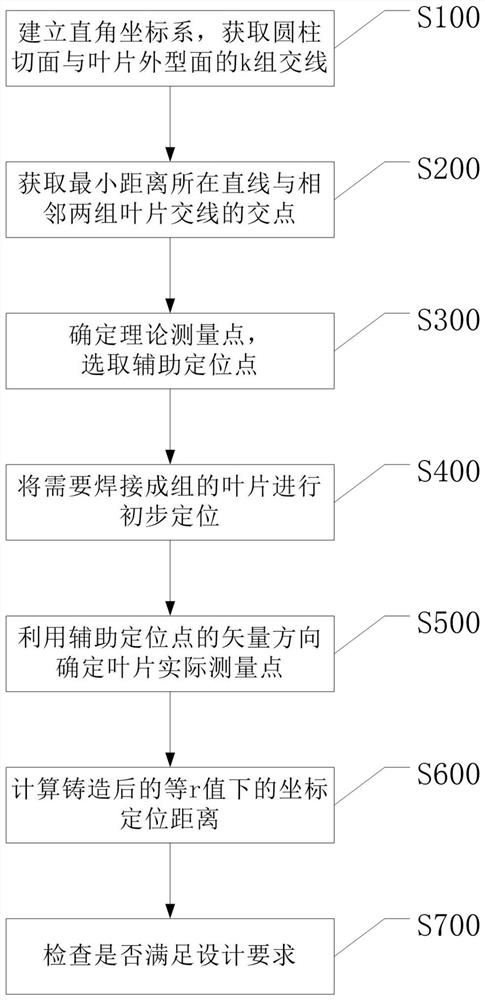
The invention belongs to the technical field of aero-engine production, and relates to a turbine guide vane welding and positioning method, which comprises the following steps: when welding and positioning turbine guide vanes, establishing a three-dimensional rectangular coordinate system, and measuring the minimum distance between two adjacent groups of vanes under equal cylindrical section radiuses; finding a theoretical measurement point corresponding to the minimum distance of the blade, finding a theoretical measurement point at the tail edge under the equal cylindrical section radius, finding an auxiliary positioning point corresponding to the theoretical measurement point, and completing theoretical calculation; when the blade is actually positioned and adjusted, the actual measurement point of the blade is found through the auxiliary positioning point, and then effective coordinate positioning and coordinate system checking can be carried out by comparing two distance difference values between the theoretical measurement point and the actual measurement point; by means of the vector positioning method, the problem that the positioning error is large due to the fact that a corresponding theoretical measuring point cannot be found on the blade outer profile due to blade casting deviation in the actual blade positioning process is solved, and the positioning accuracy is improved.

Description

technical field [0001] The application belongs to the technical field of aero-engine production, and in particular relates to a method for welding and positioning turbine guide vanes. Background technique [0002] When casting turbine guide vanes, in order to reduce the difficulty of casting, turbine guide vanes are often cast by a single vane, and two or three vanes are welded into groups for processing. [0003] At present, blade casting generally adopts the method of six-point positioning to establish the coordinate system. That is, six points are selected on the blade to determine the six degrees of freedom of the blade. The positioning points are generally set on the surface of the blade body and the flow channel of the edge plate, and then the successive approximation method is used to find the six positioning points through continuous iteration, so as to establish starting coordinate system. When welding the blades into groups, generally follow the six-point positio...

Claims


Application Information

Patent Timeline
IPC IPC(8): G01B21/00B23K37/00
CPCG01B21/00B23K37/00Y02P70/50
Inventor 屈云凤崔兴张志强陶一鸾徐景亮孙传石
Owner AECC SHENYANG ENGINE RES INST
Learn More